
Vacuum Line 5.3 Vortec Vacuum Diagram
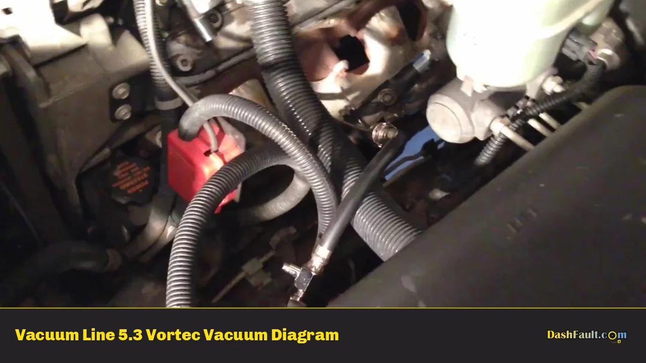
So, you're diving into the vacuum system on your 5.3 Vortec. Smart move. Understanding this system is crucial, not just for keeping your engine running smoothly, but also for diagnosing performance issues, improving fuel economy, and even tackling modifications. Think of it as the circulatory system of your engine's ancillary functions. This article will give you the roadmap you need.
Purpose of Understanding the 5.3 Vortec Vacuum Diagram
Why should you care about a vacuum diagram? Here's the breakdown:
- Troubleshooting: Vacuum leaks can mimic a whole host of other engine problems (poor idle, stalling, lean codes). Knowing the vacuum line routing allows you to systematically track down the culprit.
- Repair & Replacement: Lines become brittle, crack, and disconnect over time. A diagram tells you where each line goes, avoiding costly misconnections.
- Performance Tuning: Many aftermarket components rely on vacuum signals (boost gauges, adjustable fuel pressure regulators). Understanding the system is critical for safe and effective modifications.
- Engine Swaps & Conversions: If you're transplanting a 5.3 Vortec into another vehicle, or doing a major rebuild, the vacuum layout is a crucial reference.
- Learning Engine Management: Understanding vacuum systems is a gateway to understanding broader engine management principles.
Key Specs and Main Parts of the 5.3 Vortec Vacuum System
The 5.3 Vortec's vacuum system might seem complex, but it revolves around a few key components. Knowing these intimately makes the diagram much easier to decipher.
Main Components:
- Intake Manifold: This is the heart of the vacuum system. It's where the engine's vacuum is created as the pistons move down on the intake stroke.
- Vacuum Lines (Hoses): These are the arteries and veins of the system, carrying vacuum to various components. They come in different sizes and materials, and it’s crucial to use the correct type for each application.
- PCV Valve (Positive Crankcase Ventilation): This valve regulates the vacuum applied to the crankcase, drawing out blow-by gases and routing them back into the intake manifold to be burned. A faulty PCV valve is a common source of vacuum leaks.
- EVAP System (Evaporative Emission Control): This system captures fuel vapors from the fuel tank and prevents them from escaping into the atmosphere. Vacuum is used to purge these vapors into the engine to be burned. Key components include the EVAP canister, purge valve, and vent valve.
- Brake Booster: This utilizes vacuum to provide power assist to the brakes, making it easier to stop the vehicle.
- HVAC System (Heating, Ventilation, and Air Conditioning): Vacuum is often used to control blend doors and mode doors within the HVAC system, directing airflow.
- EGR Valve (Exhaust Gas Recirculation): Some 5.3 Vortec engines utilize vacuum to control the EGR valve, which recirculates a portion of the exhaust gas back into the intake manifold to reduce NOx emissions.
- Throttle Body: Though electronically controlled on many newer 5.3L variants, vacuum ports may still be present, used for certain sensors or auxiliary functions.
Important Specs to Note:
- Vacuum Measurement: Vacuum is typically measured in inches of mercury (in. Hg) or kilopascals (kPa). A healthy 5.3 Vortec should pull around 17-22 in. Hg at idle.
- Hose Sizes: Vacuum lines come in a variety of inner diameters (ID), typically ranging from 1/8" to 3/8". Using the wrong size hose can lead to leaks or improper component operation.
- Hose Material: Vacuum lines should be made of a material that is resistant to fuel, oil, and heat. Common materials include rubber, silicone, and plastic.
- Check Valves: These one-way valves prevent vacuum from bleeding off in certain parts of the system. Ensure proper orientation when replacing them.
Understanding Vacuum Diagram Symbols
Vacuum diagrams use standardized symbols to represent different components and lines. Learning to "read" these symbols is essential.
Line Types:
- Solid Line: Typically represents a vacuum line.
- Dashed Line: May represent a reference signal wire or a control wire associated with a vacuum-operated component.
- Dotted Line: Usually indicates a vent line or a line that's open to the atmosphere.
Color Coding:
While not universally standardized, color coding can provide additional clarity on some diagrams. However, always cross-reference color coding with the actual component labels.
- Black: Often represents the main vacuum source from the intake manifold.
- Green: Sometimes used for EVAP system lines.
- Red: Can indicate a line associated with the brake booster.
Component Symbols:
These symbols vary slightly depending on the manufacturer, but here are some common ones:
- Circle with a "V" inside: Vacuum reservoir.
- Square with diagonal lines: Vacuum switch.
- Small rectangle with an arrow: Check valve (arrow indicates the direction of flow).
- Cylinder with a line connected: Vacuum actuator.
How the 5.3 Vortec Vacuum System Works
The 5.3 Vortec's vacuum system is all about using engine vacuum to operate various components. Here's a simplified explanation:
- Vacuum Creation: As the engine runs, the pistons create a vacuum in the intake manifold during the intake stroke.
- Distribution: Vacuum lines are connected to the intake manifold and distribute this vacuum to different components.
- Component Activation: Vacuum actuators use the vacuum to move mechanical parts, such as blend doors in the HVAC system or the EGR valve.
- System Regulation: Valves (like the PCV valve and EVAP purge valve) regulate the amount of vacuum applied to specific components.
- Feedback & Control: Some components have sensors that monitor their operation and provide feedback to the engine control module (ECM). The ECM can then adjust the vacuum system as needed to optimize performance and emissions.
Real-World Use: Basic Troubleshooting Tips
Let's say your 5.3 Vortec has a rough idle. Here's how you can use your understanding of the vacuum system to troubleshoot the issue:
- Visual Inspection: Start by visually inspecting all vacuum lines for cracks, breaks, or disconnections. Pay close attention to lines near heat sources or areas where they might rub against other components.
- Listen for Leaks: With the engine running, listen for hissing sounds, which can indicate a vacuum leak.
- Use a Vacuum Gauge: Connect a vacuum gauge to a known vacuum port (like the one on the intake manifold). A reading that is lower than expected can indicate a vacuum leak.
- Smoke Test: A smoke test is a very effective method for finding vacuum leaks. Introduce smoke into the intake manifold and look for smoke escaping from any leaks.
- Component Testing: Use a vacuum pump to test individual components, such as the PCV valve or brake booster, to ensure they are holding vacuum properly.
- Check Valve Function: Verify proper check valve orientation and function. Disconnect the line and attempt to blow air through it in both directions. It should only allow flow in one direction.
Safety Considerations
Working with the vacuum system is generally safe, but here are a few things to keep in mind:
- Hot Surfaces: Be careful when working around hot engine components, such as the exhaust manifold.
- Fuel Lines: Avoid damaging or disconnecting fuel lines when working on the vacuum system. Fuel leaks can be a fire hazard.
- Brake Booster: The brake booster contains a vacuum reservoir. Depress the brake pedal several times with the engine off to release any stored vacuum before disconnecting the booster.
- Sharp Objects: Use caution when cutting or disconnecting vacuum lines to avoid injury from sharp tools or hose barbs.
Important Note: Vacuum leaks often throw off the air-fuel ratio, leading to the engine running lean. Extended lean operation can cause engine damage. Address vacuum leaks promptly!
With the knowledge you've gained in this article and the downloadable vacuum diagram we provide, you're well-equipped to understand and troubleshoot the vacuum system on your 5.3 Vortec. Remember to take your time, be methodical, and always prioritize safety.