
Vacuum Relief Valve Water Heater Diagram
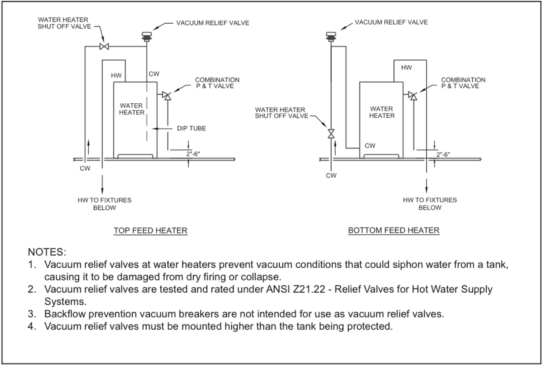
If you're tackling water heater maintenance or troubleshooting, understanding the vacuum relief valve is crucial. This seemingly small component plays a significant role in your water heater's safety and longevity. This article provides an in-depth look at the vacuum relief valve and its function within a water heater system, accompanied by a comprehensive diagram. Having a clear understanding is invaluable for repairs, upgrades, and even just gaining a better understanding of your home's plumbing.
Why Understanding the Vacuum Relief Valve Diagram Matters
A well-understood diagram allows for efficient and safe work on your water heater. Specifically, grasping the purpose and operation of the vacuum relief valve is essential for several reasons:
- Troubleshooting: Identifying and addressing issues related to vacuum buildup or valve malfunction.
- Repairing: Safely replacing a faulty valve or connecting piping.
- Preventative Maintenance: Recognizing signs of potential problems before they escalate.
- Learning: Gaining a deeper understanding of your home's plumbing systems.
Without a proper understanding of the system, you risk damaging the water heater, your plumbing, or even causing injury. Knowing the ins and outs of the vacuum relief valve, aided by a detailed diagram, allows you to confidently approach any maintenance or repair task.
Key Specs and Main Parts
The vacuum relief valve, though simple in design, is a critical safety component. Understanding its specifications and individual parts is essential.
Key Specs:
- Diameter: Typically ½-inch or ¾-inch NPT (National Pipe Thread) connection. This refers to the size of the threaded connection that screws into the water heater.
- Material: Commonly made of brass or plastic. Brass offers durability, while plastic provides corrosion resistance in certain water conditions.
- Cracking Pressure: The pressure differential required to open the valve, measured in inches of water column. This is usually very low, often around 0.5 inches. This indicates how much vacuum the valve needs to detect to open.
- Temperature Rating: The maximum operating temperature the valve can withstand, typically matching the water heater's maximum temperature setting (e.g., 210°F).
Main Parts:
- Valve Body: The main housing, usually brass or plastic, that connects to the water heater tank.
- Poppet or Disc: A small component inside the valve that seals against the seat, preventing air from entering unless a vacuum is present.
- Spring (Optional): Some vacuum relief valves utilize a light spring to help keep the poppet seated.
- Vent Opening: The opening through which air is drawn into the tank when the valve opens. This should be free of obstructions.
The valve’s purpose is to prevent vacuum conditions within the tank, which can damage the tank lining or even cause the tank to collapse. It works by allowing air to enter the tank when pressure drops below atmospheric pressure.
Symbols and Line Types on the Diagram
Understanding the symbols used on a water heater diagram, especially concerning the vacuum relief valve, is vital for proper interpretation.
- Solid Lines: Represent physical pipes or conduits carrying water or gas. The thickness often indicates the pipe diameter.
- Dashed Lines: Usually indicate control lines, electrical wiring, or hidden components.
- Valve Symbols: Valves are generally represented by circles or angled lines. A vacuum relief valve may have a specific symbol indicating its one-way air inlet functionality.
- Arrows: Indicate the direction of flow (water, air, or gas).
- Labels: Abbreviations and text descriptions clarify the function of each component. "VRV" is a common abbreviation for Vacuum Relief Valve.
- Color Coding (Less Common): Some diagrams may use color to differentiate between hot and cold water lines (red for hot, blue for cold).
Pay close attention to the placement of the vacuum relief valve in relation to the water heater tank, the cold water inlet, and the hot water outlet. The diagram will illustrate how the valve is integrated into the overall plumbing system.
How It Works
The vacuum relief valve operates on a simple principle: pressure differential. Here's a breakdown of its operation:
- Normal Operation: Under normal conditions, the pressure inside the water heater tank is at or above atmospheric pressure. The poppet or disc within the valve remains seated, preventing air from entering the tank.
- Vacuum Creation: A vacuum can occur in the tank during several scenarios:
- Water Draining: When a large volume of hot water is rapidly drained from the tank, a vacuum can form if air cannot enter to replace the water.
- Supply Interruption: If the cold water supply is interrupted, and hot water is drawn out of the tank, a vacuum can form.
- Valve Activation: As the pressure inside the tank drops below atmospheric pressure, a pressure differential is created across the valve's poppet. This pressure difference overcomes the spring tension (if present) and/or the force of atmospheric pressure, causing the poppet to lift.
- Air Intake: With the poppet open, air is drawn into the tank through the vent opening, equalizing the pressure.
- Valve Closure: Once the pressure inside the tank equalizes with atmospheric pressure, the poppet reseats, stopping the flow of air.
In essence, the valve acts as a one-way air inlet, preventing the negative pressure that could damage the tank.
Real-World Use and Basic Troubleshooting
Here are some practical troubleshooting tips related to the vacuum relief valve:
- Valve Leaking Air: A small amount of air intake is normal, especially after heavy hot water usage. However, continuous hissing or air intake could indicate a problem:
- Low Water Pressure: Check the incoming water pressure to ensure it's adequate.
- Faulty Valve: The valve may be sticking open or have a damaged poppet. Replacement is usually the best course of action.
- Tank Collapse (Rare): This is an extreme scenario, but if the vacuum relief valve fails entirely, a strong vacuum can form, potentially causing the tank to deform or collapse. Look for signs of implosion. Replace the water heater and valve immediately.
- Preventative Maintenance: Periodically inspect the valve for corrosion or debris. Clean the vent opening to ensure it's unobstructed.
Safety Considerations
Working on a water heater involves inherent risks. Pay close attention to these safety aspects, especially when dealing with the vacuum relief valve:
- Power Disconnection: Always disconnect the power supply to the water heater (circuit breaker) before performing any maintenance or repairs.
- Water Shut-Off: Turn off the cold water supply to the water heater before disconnecting any plumbing connections.
- Hot Water: Be extremely cautious of hot water. Allow the water to cool down before draining the tank.
- Gas Lines: If you have a gas water heater, be extremely careful when working near the gas line. If you suspect a gas leak, evacuate the area and call a qualified technician.
- Valve Location: The vacuum relief valve is usually installed on the top of the water heater. Access can be restricted, making it necessary to carefully approach repairs.
- Component Risk: The vacuum relief valve itself does not present a shock risk, but improper handling of the water heater connections could cause burns.
Remember to always consult the water heater manufacturer's instructions and local plumbing codes before attempting any work.
We have a detailed vacuum relief valve water heater diagram available for download. It provides a visual guide to the valve's components and its placement within the system. This resource can be an invaluable aid during troubleshooting and repairs.