
Vacuum Subaru Intake Manifold Diagram
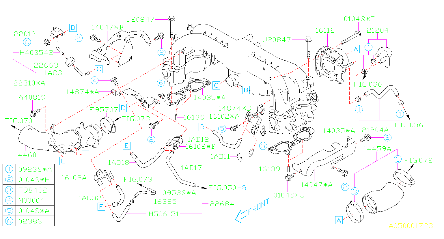
The vacuum system in your Subaru's intake manifold might seem like a complex web of hoses, but understanding its function is crucial for maintaining optimal engine performance and diagnosing various issues. This article serves as a comprehensive guide to interpreting a vacuum diagram specific to Subaru intake manifolds, empowering you to tackle repairs, modifications, and troubleshooting with confidence.
Purpose of the Vacuum Diagram
A vacuum diagram is essentially a roadmap for your Subaru's vacuum system. It outlines the connections between various components, including the intake manifold, sensors, solenoids, and other vacuum-operated devices. Understanding the diagram is vital for several reasons:
- Troubleshooting: Vacuum leaks can cause a wide range of engine problems, from poor idling and hesitation to decreased fuel economy and even a check engine light. The diagram helps you pinpoint the source of the leak by showing you where to look.
- Repairs: When replacing vacuum hoses or components, the diagram ensures you reconnect everything correctly, preventing further issues.
- Modifications: If you're modifying your Subaru's engine, such as installing a new intake manifold or adding a boost gauge, the diagram helps you understand how the vacuum system will be affected and how to make the necessary adjustments.
- Learning: Even if you're not currently experiencing any problems, studying the diagram is a great way to learn about the inner workings of your Subaru's engine management system.
Key Specs and Main Parts
While specific components may vary depending on the Subaru model and year, the core principles remain the same. Here's a breakdown of the key parts typically found within a Subaru intake manifold vacuum system:
- Intake Manifold: The central hub of the vacuum system. It distributes air to the cylinders and provides a source of vacuum for various components.
- Vacuum Hoses: These rubber or silicone hoses connect the intake manifold to other components, carrying vacuum pressure. Different sizes and materials might be used depending on the application.
- Check Valves: These one-way valves allow air to flow in only one direction, preventing backflow and maintaining vacuum in specific parts of the system. A common example is the PCV (Positive Crankcase Ventilation) valve.
- Solenoid Valves: Electrically controlled valves that regulate vacuum flow to various components, such as the boost control solenoid (on turbocharged models), the EGR (Exhaust Gas Recirculation) valve solenoid, and purge control solenoid.
- Sensors: Various sensors rely on vacuum pressure to function correctly, including the MAP (Manifold Absolute Pressure) sensor, which measures the pressure inside the intake manifold.
- Vacuum Reservoir: A small container that stores vacuum pressure, ensuring a consistent supply to certain components, especially during periods of high engine load.
- PCV Valve: This valve is part of the Positive Crankcase Ventilation system. It uses vacuum to draw blow-by gases from the crankcase and recirculate them back into the intake manifold for combustion.
- EGR Valve: The Exhaust Gas Recirculation valve uses vacuum to introduce exhaust gases back into the intake manifold, lowering combustion temperatures and reducing NOx emissions. This is typically electronically controlled via a solenoid.
- Fuel Pressure Regulator: Some fuel pressure regulators use a vacuum line from the intake manifold to adjust fuel pressure based on engine load.
Symbols, Lines, and Colors in the Diagram
Subaru vacuum diagrams use a standardized set of symbols and conventions to represent different components and connections. Understanding these symbols is crucial for interpreting the diagram correctly:
- Solid Lines: Typically represent vacuum hoses. The thickness of the line may indicate the hose diameter.
- Dashed Lines: Often indicate electrical connections or signal lines.
- Arrows: Indicate the direction of airflow or vacuum flow.
- Colors: While not universally standardized across all diagrams, colors are often used to differentiate between different types of hoses or vacuum lines. For example, one color might represent a line connected to the PCV system, while another represents a line connected to the fuel pressure regulator.
- Component Symbols: Each component, such as a solenoid valve or check valve, will have a specific symbol. These symbols are usually explained in a key or legend on the diagram.
- Vent Symbols: A vent symbol (often a small triangle or circle) will indicate a line open to atmosphere.
Look for the legend on the diagram. This legend is the key to understanding the various symbols.
How It Works: The Vacuum Network
The intake manifold creates a vacuum due to the downward movement of the pistons during the intake stroke. This vacuum is then harnessed to operate various components. The engine creates a vacuum when the throttle plate is closed or partially closed. The degree of vacuum can vary based on throttle position. The intake manifold vacuum pulls air out of various components, like the brake booster, fuel pressure regulator, and EGR valve, as well as the crankcase via the PCV system. The network of hoses and valves precisely controls where this vacuum is applied and when.
For example, the PCV valve uses vacuum to draw blow-by gases from the crankcase, preventing pressure buildup and reducing emissions. The EGR valve uses vacuum (controlled by a solenoid) to recirculate exhaust gases, lowering combustion temperatures. The brake booster utilizes vacuum to assist with braking, reducing the amount of force required to depress the brake pedal. Modern systems are computer-controlled with solenoids and sensors adjusting vacuum based on numerous parameters.
Real-World Use: Basic Troubleshooting Tips
Here are a few basic troubleshooting tips when using a vacuum diagram:
- Identify the Symptom: What specific problem are you experiencing? Is it a rough idle, poor fuel economy, or a check engine light?
- Locate Relevant Components: Based on the symptom, use the vacuum diagram to identify the components that could be involved. For instance, a rough idle might point to a vacuum leak near the intake manifold or PCV valve.
- Inspect Vacuum Hoses: Carefully inspect all vacuum hoses connected to the relevant components for cracks, leaks, or disconnections. Use your fingers to gently squeeze the hoses and check for brittleness.
- Check Valves and Solenoids: Test check valves to ensure they are functioning correctly, allowing airflow in only one direction. Use a multimeter to test solenoid valves for proper operation.
- Use a Vacuum Gauge: A vacuum gauge can be connected to various points in the system to measure vacuum pressure and identify leaks.
- Smoke Test: A smoke test is an effective way to locate vacuum leaks. Smoke is introduced into the vacuum system, and any leaks will be visible as smoke escaping from the hoses or components.
- Listen Carefully: A hissing sound can indicate a vacuum leak.
Safety Considerations
Working with the vacuum system involves some safety considerations:
- Hot Components: The intake manifold and surrounding components can get very hot, especially after the engine has been running. Allow the engine to cool down completely before working on the vacuum system.
- Fuel Lines: Be careful not to damage any fuel lines when working around the intake manifold. Leaks from fuel lines can be a serious fire hazard.
- Electrical Connections: Disconnect the battery before working on any electrical components, such as solenoid valves.
- Sharp Edges: Be aware of sharp edges on the intake manifold and other components. Wear gloves to protect your hands.
- Boost Pressure (Turbocharged Models): If working on a turbocharged Subaru, be aware of residual boost pressure in the system. Depressurize the system properly before disconnecting any hoses.
The PCV system deals with crankcase vapors, which can be flammable. Ensure adequate ventilation when working on this system.
By understanding your Subaru intake manifold's vacuum diagram, you gain valuable knowledge for diagnosing and repairing issues. Remember to work safely, double-check your connections, and consult the diagram frequently.
We have access to various Subaru intake manifold vacuum diagrams. Contact us for the specific diagram relevant to your year and model. We can provide the file for you to download.