Vehicle Air Conditioning System Diagram
Alright, let's dive into the often-overlooked, but incredibly crucial, world of automotive air conditioning. This article will serve as your guide to understanding the AC system diagram. Think of it as the roadmap to keeping your cool on those scorching summer days. We'll break down the components, decipher the symbols, and even give you some basic troubleshooting tips. Trust me, even if you're not planning a full system rebuild, understanding this diagram can be a lifesaver when trying to diagnose a simple issue.
Why Bother With an AC System Diagram?
Why should you, an experienced DIYer or car enthusiast, care about an AC system diagram? There are several compelling reasons:
- Troubleshooting: Diagnosing AC problems without understanding the system layout is like navigating a maze blindfolded. The diagram allows you to trace the flow of refrigerant and pinpoint potential issues.
- Repairs: Whether you're replacing a compressor, condenser, or simply recharging the system, the diagram provides a visual reference to ensure correct connections and component placement.
- Modifications: Thinking of upgrading your AC system? The diagram helps you understand compatibility and plan your modifications effectively.
- Learning: Gaining a deeper understanding of your vehicle's systems empowers you to take better care of it. Knowledge is power!
Key Specs and Main Parts of the AC System
Before we dissect the diagram itself, let's review the core components of a typical automotive AC system. Keep in mind that specific configurations may vary slightly depending on the vehicle make and model.
- Compressor: The heart of the system. It pressurizes the refrigerant, raising its temperature and allowing it to flow through the system.
- Condenser: Located in front of the radiator, the condenser cools the high-pressure refrigerant, causing it to condense from a gas to a liquid.
- Receiver-Drier (or Accumulator): This component filters out moisture and debris from the refrigerant. In systems with a TXV (Thermostatic Expansion Valve), it's called a receiver-drier; in systems with an orifice tube, it's called an accumulator.
- Expansion Valve (or Orifice Tube): This metering device controls the flow of refrigerant into the evaporator. The TXV is a more sophisticated valve that automatically adjusts refrigerant flow based on temperature and pressure, while the orifice tube is a simpler, fixed-size restriction.
- Evaporator: Located inside the passenger compartment, the evaporator absorbs heat from the air passing over it, cooling the cabin.
- Refrigerant Lines: Hoses and pipes that connect all the components, carrying the refrigerant throughout the system.
- Pressure Switches: These sensors monitor the refrigerant pressure and protect the system from damage by shutting off the compressor if the pressure is too high or too low.
Key Specs: Refrigerant type (e.g., R-134a, R-1234yf) and refrigerant charge amount are critical specs, usually found on a sticker under the hood or in the owner's manual. Using the wrong refrigerant or incorrect charge can severely damage the system.
Deciphering the Symbols: Lines, Colors, and Icons
An AC system diagram is a schematic representation, not a literal picture of the components. Understanding the symbols is crucial to interpreting the diagram correctly.
- Lines: Different types of lines represent different things:
- Solid lines typically indicate refrigerant lines.
- Dashed lines usually represent electrical wiring or vacuum lines.
- Dotted lines might indicate control linkages or mechanical connections.
- Colors: While not always standardized, colors can be helpful.
- Red often indicates high-pressure lines.
- Blue often indicates low-pressure lines.
- However, always refer to the diagram's legend for specific color meanings.
- Icons: These represent the individual components. Common icons include:
- Compressor: Often a stylized pump symbol.
- Condenser: Usually depicted as a series of zig-zag lines.
- Receiver-Drier/Accumulator: A cylindrical shape with desiccant material indicated.
- Expansion Valve: A valve symbol, often with a temperature sensor connected.
- Orifice Tube: A small restriction symbol.
- Evaporator: Similar to the condenser, but often smaller and located inside a rectangle representing the HVAC unit.
- Pressure Switches: A switch symbol with pressure indication.
Important Note: Always refer to the specific diagram's legend for the definitive meaning of each symbol and color. These can vary slightly between manufacturers and models.
How the AC System Works: A Refrigerant's Journey
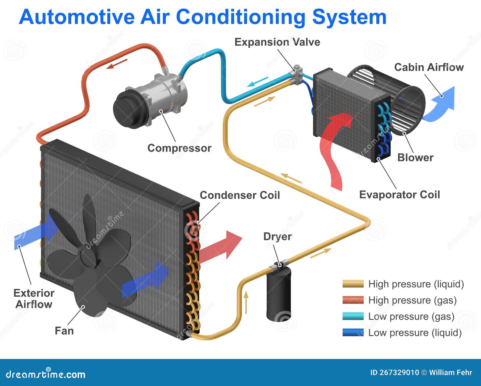
The AC system operates on the principle of heat transfer. Refrigerant cycles through the system, absorbing heat from the passenger compartment and releasing it outside the vehicle. Here's a simplified breakdown:
- Compression: The compressor pumps low-pressure, low-temperature refrigerant vapor into a high-pressure, high-temperature vapor.
- Condensation: The high-pressure, high-temperature refrigerant vapor flows to the condenser, where it releases heat to the surrounding air and condenses into a high-pressure, high-temperature liquid.
- Metering: The high-pressure liquid refrigerant flows to the expansion valve (or orifice tube), where its pressure is reduced, causing it to rapidly cool.
- Evaporation: The low-pressure, low-temperature refrigerant flows into the evaporator, where it absorbs heat from the air passing over it, causing the air to cool and the refrigerant to boil back into a low-pressure, low-temperature vapor.
- Return: The low-pressure, low-temperature refrigerant vapor returns to the compressor, and the cycle repeats.
Real-World Use: Basic Troubleshooting Tips
Armed with your newfound knowledge of the AC system diagram, you can start diagnosing common issues. Remember to always consult your vehicle's service manual for specific procedures and safety precautions.
- No Cold Air:
- Check the refrigerant level. Low refrigerant is a common cause. Use the diagram to locate the service ports.
- Inspect the compressor clutch. Is it engaging when the AC is turned on? The diagram can help you trace the wiring to the compressor.
- Look for leaks. Use the diagram to identify potential leak points, such as connections and the condenser.
- Weak Airflow:
- Check the blower motor. The diagram will show the blower motor's location and wiring.
- Inspect the cabin air filter. A clogged filter restricts airflow.
- Unusual Noises:
- Listen for noises coming from the compressor. The diagram helps you pinpoint the compressor's location for closer inspection.
Safety First! Risky Components and Procedures
Working with AC systems involves potentially hazardous components and procedures. Always prioritize safety:
- Refrigerant: Refrigerant can cause frostbite and asphyxiation. Work in a well-ventilated area and wear appropriate protective gear, including gloves and eye protection.
- High Pressure: AC systems operate under high pressure. Never disconnect lines or components without properly discharging the system first. Improper handling can result in serious injury.
- Electrical Components: The AC system includes electrical components. Disconnect the battery before working on the electrical system to prevent shocks.
- Proper Disposal: Refrigerant is harmful to the environment. Never vent refrigerant into the atmosphere. Dispose of it properly according to local regulations.
Warning: If you're not comfortable working with refrigerant or electrical components, it's best to leave AC repairs to a qualified professional. Your safety and the environment are paramount.
With this knowledge, you're well-equipped to understand and utilize an AC system diagram for troubleshooting, repairs, or even modifications. Remember to always refer to your vehicle's specific diagram and service manual for the most accurate information. And most importantly, stay safe!
We have a sample AC system diagram file available for download. You can use this to practice identifying components and tracing refrigerant flow. We'll also periodically update the diagrams to keep you updated with the latest vehicle models.