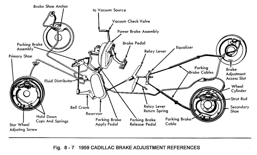
Vintage Cadillac Brake Parts Diagram
Let's dive into something crucial for keeping those classic Cadillacs rolling smoothly and safely: the vintage Cadillac brake parts diagram. Whether you're embarking on a full restoration, tackling a brake repair, or just deepening your understanding of your car's mechanics, a good diagram is an invaluable resource. Think of it as the Rosetta Stone for your braking system. We’ll walk you through understanding it, troubleshooting with it, and using it safely.
Purpose of a Vintage Cadillac Brake Parts Diagram
Why bother with a diagram? Simple: accuracy and efficiency. Trying to work on a complex system like brakes without a clear visual guide is a recipe for frustration, wasted time, and potentially dangerous mistakes. The diagram serves several key purposes:
- Identification: Quickly and accurately identify each component of the braking system. No more guessing!
- Ordering Parts: Ensure you're ordering the correct replacement parts with the right specifications. Part numbers are often included directly on the diagram or referenced nearby.
- Assembly/Disassembly: Follow the correct sequence for taking apart and putting back together the brake system, minimizing the risk of damage or incorrect assembly.
- Troubleshooting: Diagnose problems by understanding how the components interact and tracing potential issues within the system.
- Learning: Gain a deeper understanding of how your Cadillac's braking system functions as a whole.
Key Specs and Main Parts
Vintage Cadillac braking systems vary significantly depending on the year and model. However, some core components are common to most models. A typical diagram will illustrate the following:
Hydraulic System
- Master Cylinder: The heart of the system, it converts mechanical force from the brake pedal into hydraulic pressure. The diagram will show its location, connection to the brake lines, and internal components like pistons and seals.
- Brake Lines: These are the arteries of the system, carrying brake fluid to each wheel. The diagram will show their routing, connectors (fittings), and any associated brackets or clips.
- Wheel Cylinders (Drum Brakes) or Calipers (Disc Brakes): These convert hydraulic pressure back into mechanical force to apply the brakes at each wheel. The diagram will detail their construction, mounting, and connection to the brake shoes or pads.
- Brake Hoses: Flexible hoses connect the brake lines to the calipers, allowing for suspension movement. The diagram is critical for identifying the correct length and fittings.
- Proportioning Valve: This valve regulates brake pressure between the front and rear wheels to prevent wheel lockup during hard braking. The diagram will show its location in the brake line circuit.
Mechanical System (Often Drum Brakes)
- Brake Shoes: These are the friction surfaces that press against the brake drums to slow the vehicle. The diagram will detail their shape, lining material, and mounting hardware.
- Brake Drums: The rotating cylinders that the brake shoes press against.
- Wheel Cylinders (Within Drum Brakes): Actuate the brake shoes.
- Return Springs: These springs pull the brake shoes away from the drums when the brake pedal is released.
- Adjusters: Used to maintain the correct clearance between the brake shoes and drums.
- Parking Brake Cables and Linkages: These provide a mechanical means of applying the brakes when the vehicle is parked.
Power Booster (If Equipped)
- Vacuum Booster (or Hydroboost): Uses engine vacuum (or hydraulic pressure in the case of Hydroboost) to assist the driver in applying the brakes. The diagram will show its connection to the master cylinder, vacuum lines (or power steering lines in the case of hydroboost), and check valves.
Key Specs: The diagram might not explicitly state specs, but it will provide clues to them. For example, the size and type of brake lines, the thread pitch of fittings, and the dimensions of brake shoes or pads can be inferred from the diagram. These are crucial for ordering the correct replacement parts.
Symbols on the Diagram
Understanding the symbols used on the diagram is essential for interpreting the information it conveys. While specific symbols may vary slightly depending on the source, some common conventions include:
- Solid Lines: Typically represent brake lines or mechanical linkages.
- Dashed Lines: Often indicate vacuum lines, electrical wiring, or hidden components.
- Arrows: Show the direction of fluid flow or movement.
- Circles and Squares: Represent components like valves, cylinders, or mounting points.
- Color Coding: Some diagrams use color to differentiate between different circuits or types of fluid. For example, red might indicate the front brake circuit and blue the rear. However, color is less common in older, black-and-white diagrams.
A legend or key should accompany the diagram to explain the meaning of each symbol. Pay close attention to this legend before attempting to interpret the diagram.
How It Works
The diagram helps visualize the flow of hydraulic pressure from the master cylinder, through the brake lines, to the wheel cylinders or calipers. Understanding this flow is crucial for troubleshooting. Consider this simplified explanation, guided by the diagram:
- When you press the brake pedal, the master cylinder generates hydraulic pressure.
- This pressure travels through the brake lines to each wheel.
- At the wheels, the pressure forces the wheel cylinders (drum brakes) or calipers (disc brakes) to activate, pushing the brake shoes against the drums or the brake pads against the rotors.
- This friction slows or stops the vehicle.
- When you release the brake pedal, the pressure is released, and return springs pull the brake shoes or pads back to their resting position.
The diagram will show how each component is connected and how it contributes to this overall process. By tracing the lines and understanding the function of each part, you can gain a clear understanding of how the braking system works.
Real-World Use: Basic Troubleshooting
The diagram is an invaluable tool for diagnosing brake problems. Here are a few examples:
- Soft Brake Pedal: The diagram can help you identify potential causes, such as air in the brake lines, a leaking master cylinder, or a leaking wheel cylinder/caliper. By visually tracing the system, you can pinpoint the most likely source of the leak.
- Brake Pulling to One Side: The diagram can help you identify potential causes, such as a sticking caliper, a contaminated brake shoe/pad, or a blocked brake line on one side.
- Brake Squeal or Grinding: While the diagram won't directly tell you the cause of the noise, it can help you identify the components that are likely to be worn or damaged, such as brake shoes, pads, or rotors.
When troubleshooting, always start by visually inspecting the components shown on the diagram. Look for leaks, damage, or excessive wear. Compare the condition of the components on both sides of the vehicle to identify any discrepancies.
Safety Considerations
Working on brakes is serious business. A faulty braking system can have catastrophic consequences. Here are some key safety considerations:
- Brake Fluid: Brake fluid is corrosive and can damage paint and skin. Wear gloves and eye protection when handling it.
- Asbestos (Older Models): Brake linings on older vehicles may contain asbestos. Take precautions to avoid inhaling asbestos dust when working on these systems. Wear a respirator and wet down the components before removing them.
- Brake Springs: Brake springs are under tension and can cause serious injury if they are not handled properly. Use the correct tools and techniques when removing or installing them.
- Master Cylinder: The master cylinder contains pressurized brake fluid. Relieve the pressure before disconnecting any lines or components.
- Bleeding Brakes: Bleeding brakes properly is essential to ensure that the braking system functions correctly. Follow the correct bleeding procedure and use the correct type of brake fluid.
- Testing: After completing any brake work, thoroughly test the system in a safe environment before driving on public roads.
Never compromise on safety. If you are not comfortable working on brakes, take your vehicle to a qualified mechanic. Brakes are one of the most critical safety systems on your car and should only be serviced by someone with the necessary knowledge and experience.
Remember to consult your specific Cadillac's service manual for detailed procedures and specifications. The diagram is a guide, but the manual provides the definitive instructions.
We have a high-resolution, printable PDF version of a common vintage Cadillac brake parts diagram available for download. This file includes detailed views of the hydraulic system, drum brake assemblies, and other critical components. Download the diagram and print it out for easy reference in your garage.