Volkswagen Alternator Wiring Diagram
Alright, let's dive into Volkswagen alternator wiring diagrams. Whether you're battling a charging issue, planning an electrical upgrade, or just want a deeper understanding of your VW, understanding the alternator wiring is crucial. This isn't just about blindly following wires; it's about understanding the *why* behind each connection. This article will break down the essential components, symbols, and troubleshooting tips you need to confidently tackle alternator wiring on your VW.
Purpose: Why Bother with the Wiring Diagram?
Why spend time deciphering a wiring diagram? Several reasons. Primarily, it's indispensable for:
- Troubleshooting Charging Problems: Is your battery light on? Is your battery draining inexplicably? The wiring diagram is your roadmap for tracing voltage drops, shorts, and open circuits within the charging system.
- Performing Repairs: Replacing a faulty wire, connector, or even the alternator itself requires a clear understanding of the connections. Accidentally swapping wires can lead to damage.
- Electrical Upgrades/Modifications: Adding auxiliary lights, a powerful sound system, or other electrical components often necessitates tapping into the vehicle's charging system. You need to know where to safely connect without overloading circuits.
- Learning Vehicle Electrical Systems: Even if you're not currently having problems, studying the wiring diagram provides a foundational understanding of how the entire electrical system interacts.
- Verifying Correct Installation: If a previous owner (or even a shop) worked on the wiring, the diagram ensures everything is connected as intended.
Think of the wiring diagram as the electrical blueprint for your VW. Without it, you're essentially guessing when working on the charging system.
Key Specs and Main Parts of a VW Alternator Circuit
Before we examine the diagram itself, let's review the core components involved in a typical VW alternator circuit:
- Alternator: The heart of the charging system. It converts mechanical energy from the engine into electrical energy to charge the battery and power the vehicle's electrical loads. Key specs include amperage output (e.g., 90A, 120A) and voltage regulation (typically around 14.4V).
- Battery: Stores electrical energy and provides the initial current to start the engine.
- Voltage Regulator: Controls the alternator's output voltage. In many modern VWs, the regulator is integrated into the alternator itself. Older models might have an external regulator.
- Ignition Switch: Controls the flow of power to various circuits, including the alternator's exciter circuit.
- Battery Light (Charging Indicator): Located on the instrument cluster. It illuminates when the alternator isn't producing sufficient voltage, indicating a charging problem.
- Fuses and Relays: Protect the circuit from overcurrents and provide switching capabilities for various components.
- Wiring Harness: The network of wires that connect all the components.
Common VW alternators include Bosch and Valeo units. Amperage output varies depending on the model and year. Higher output alternators are often found in vehicles with more electrical accessories (e.g., air conditioning, heated seats).
Wiring Diagram Breakdown: Main Connections
Now, let's consider the typical connections you'll find in a VW alternator wiring diagram:
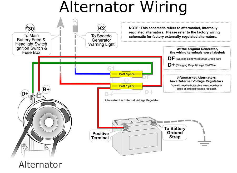
- B+ (Battery Positive): A heavy-gauge wire connecting the alternator's main output terminal directly to the positive (+) terminal of the battery (often through a fuse or fusible link). This is the primary charging path.
- D+ (Exciter Wire) or L Terminal: Connected to the battery light (charging indicator) on the instrument cluster and sometimes through the ignition switch. This wire provides the initial excitation current to start the alternator charging. When the ignition is on but the engine isn't running, this wire provides a ground path for the battery light, causing it to illuminate. Once the alternator starts generating voltage, it supplies voltage to this wire, extinguishing the battery light.
- Ground: A connection from the alternator casing to the vehicle's chassis or engine block, providing a low-resistance path for current to return to the battery. Proper grounding is essential for correct alternator operation.
- Field Terminal (Rare on Modern VWs): On some older alternators, there might be a separate field terminal (often labeled 'F') that connects to the voltage regulator. This allows the regulator to control the alternator's field current, thereby regulating its output voltage.
- Data Connection (CAN Bus): Many modern VWs utilize a Controller Area Network (CAN bus) to communicate between the engine control unit (ECU) and the alternator. This allows the ECU to monitor and control the alternator's output based on various factors, such as engine load and battery state.
Symbols: Deciphering Lines, Colors, and Icons
A wiring diagram uses standard symbols to represent electrical components and connections. Here's a breakdown of common symbols:
- Solid Lines: Represent wires. The thickness of the line often indicates the gauge (thickness) of the wire – thicker lines mean larger gauge wires capable of carrying more current.
- Dashed Lines: Often represent shielded cables or connections within a component (e.g., inside the alternator).
- Color Codes: Wires are color-coded to help identify them. Common colors include Red (power), Black (ground), Brown (ground - particularly for VW), Blue, Yellow, Green, and White. The diagram will typically have a legend explaining the color codes.
- Circles: Represent terminals or connection points.
- Rectangles: Represent components like fuses, relays, and switches.
- Ground Symbol: Looks like an inverted triangle or a series of horizontal lines decreasing in length.
- Alternator Symbol: A stylized representation of an alternator, often resembling a dynamo.
- Battery Symbol: A series of long and short parallel lines (representing the battery cells).
Always refer to the legend or key on the wiring diagram to understand the specific symbols used for your VW model.
How It Works: The Alternator Circuit in Action
Here's a simplified explanation of how the alternator circuit functions:
- When the ignition switch is turned on, voltage is applied to the exciter wire (D+ or L terminal) of the alternator. This provides a small current that initiates the alternator's field winding.
- As the engine starts and the alternator begins to rotate, the rotating magnetic field induces a voltage in the stator windings.
- This voltage is rectified (converted from AC to DC) by the rectifier diodes within the alternator.
- The voltage regulator monitors the output voltage and adjusts the field current to maintain a consistent output voltage (typically around 14.4V).
- The alternator's output (B+ terminal) provides current to charge the battery and power the vehicle's electrical loads.
Essentially, the alternator acts as a constant voltage source, ensuring that the battery remains charged and the vehicle's electrical systems function correctly.
Real-World Use: Basic Troubleshooting Tips
Here are some basic troubleshooting tips using the wiring diagram:
- Battery Light On: Check the exciter wire (D+ or L) for voltage with the ignition on but the engine not running. If there's no voltage, trace the wire back to the ignition switch or instrument cluster, looking for breaks or loose connections. If the wire has voltage, the fault is likely inside the alternator.
- No Charging: Check the B+ terminal for voltage with the engine running. If there's no voltage (or significantly lower than battery voltage), check the B+ wire for breaks, corrosion, or a blown fuse/fusible link. Also, check the alternator ground connection.
- Overcharging: Suspect a faulty voltage regulator. This can cause the battery to overheat and potentially damage other electrical components. Use a multimeter to measure the battery voltage while the engine is running. If it's significantly higher than 14.4V, replace the alternator or voltage regulator (if it's a separate component).
- Voltage Drop Testing: Use a multimeter to measure the voltage drop across various points in the circuit. Excessive voltage drops indicate resistance (e.g., due to corrosion or loose connections) that can impede current flow.
Always consult the specific wiring diagram for your VW model. Wiring configurations can vary significantly depending on the year, engine type, and optional equipment.
Safety: Highlighting Risky Components
Working with automotive electrical systems can be dangerous. Here are some key safety precautions:
- Disconnect the Battery: Before working on any electrical component, disconnect the negative (-) terminal of the battery. This prevents accidental shorts and electrical shocks.
- Use Proper Tools: Use insulated tools to avoid short circuits.
- Work in a Well-Ventilated Area: Battery charging can produce explosive gases.
- Be Aware of Capacitors: Some electrical components contain capacitors that can store a charge even after the battery is disconnected. Discharge capacitors before handling them.
- Fuses Protect: Never bypass or increase the amperage rating of a fuse. Fuses are designed to protect the circuit from overcurrents. Bypassing them can lead to fires.
The B+ terminal and the battery positive terminal are always live and carry a significant amount of current. Exercise extreme caution when working around these components.
We have a PDF copy of a generic VW alternator wiring diagram available for download. This should give you a good starting point, but remember to always use the specific diagram for your vehicle.