
Voltage Regulator Wiring Diagram Ford
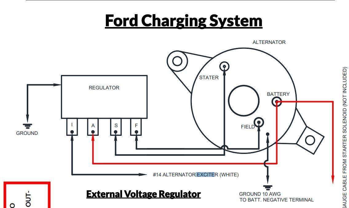
Alright, let's dive into the wiring diagram of a Ford voltage regulator. Whether you're troubleshooting a charging issue, planning an upgrade, or just want to better understand your vehicle's electrical system, this is a crucial piece of the puzzle. We're going to break down the diagram, explain its components, and give you some practical advice. I know electrical diagrams can look intimidating, but we’ll demystify it together.
Purpose of the Voltage Regulator Wiring Diagram
The wiring diagram for your Ford's voltage regulator is essentially a roadmap of its electrical connections. Think of it as the blueprint for how power flows to and from the regulator, ensuring your battery gets the proper charge and your electrical system doesn't get overloaded. You'll need this diagram for several reasons:
- Troubleshooting Charging Problems: Is your battery not charging properly? The diagram helps you trace the circuit and pinpoint the faulty component – a bad wire, a corroded connector, or a failing regulator itself.
- Replacing a Faulty Regulator: Knowing the exact wiring configuration is essential for correctly hooking up a new voltage regulator. Mismatched wires can cause serious damage.
- Wiring Upgrades or Modifications: Planning to install a higher output alternator? The diagram shows you what needs to be rewired or upgraded to handle the increased amperage.
- Understanding Your Electrical System: Even if you're not currently experiencing problems, studying the diagram provides a deeper understanding of how your Ford's charging system works.
Key Specs and Main Parts
Before we get into the specifics, let's cover the key components involved in the voltage regulator circuit:
- Alternator: The heart of the charging system, driven by the engine. It generates AC voltage, which is then rectified into DC. Its output amperage and voltage rating are crucial specs.
- Voltage Regulator: The brains of the operation. It controls the alternator's output voltage, keeping it within the optimal range (typically around 13.8-14.4 volts). Older Fords often used external voltage regulators, while newer models usually integrate the regulator into the alternator itself.
- Battery: The energy storage device. It provides power to start the engine and runs electrical accessories when the engine is off. The battery voltage and cold cranking amps (CCA) are important.
- Wiring Harness: The network of wires that connects all the components. Pay attention to wire gauge (AWG), which indicates its current-carrying capacity.
- Fuses and Circuit Breakers: Safety devices that protect the system from overcurrent situations. Check their ampere rating.
- Ground Connections: Crucial for completing the electrical circuit. Poor ground connections are a common cause of charging problems.
For older Ford models (pre-1980s, typically), you’ll find an external voltage regulator. Common regulator types are electromechanical (using points and coils) or solid-state electronic versions.
Understanding the Symbols
Wiring diagrams use standardized symbols to represent electrical components. Let's decode some of the common ones you'll see in a Ford voltage regulator diagram:
- Solid Lines: Represent wires. The thickness of the line might (but doesn't always) indicate the wire gauge.
- Dashed Lines: Often indicate shielded wires or ground connections.
- Circles: Can represent connectors, lamps, or other small components.
- Rectangles: Typically represent larger components like the voltage regulator or alternator.
- Zigzag Lines: Usually indicate resistors.
- Coil Symbols: Represent inductors or relays.
- Ground Symbol: A series of horizontal lines decreasing in length, indicating a connection to ground (the vehicle's chassis).
Color Codes: Ford uses a standard color code for its wiring. Some common colors include:
- Red: Typically indicates a power wire connected directly to the battery.
- Black: Usually indicates a ground wire.
- Yellow: Often used for circuits that are only powered when the ignition is on.
- Green: Frequently used for circuits related to lighting or instrumentation.
The diagram will usually have a key or legend that explains any specific symbols or abbreviations used in that particular diagram. Always consult the legend!
How It Works: A Simplified Explanation
The Ford voltage regulator system basically works like this:
- The alternator, driven by the engine, generates AC voltage. This AC voltage is converted to DC by diodes inside the alternator.
- The voltage regulator monitors the output voltage of the alternator.
- If the voltage is too low, the regulator increases the current flowing through the alternator's field winding (the rotor). This increases the alternator's output.
- If the voltage is too high, the regulator decreases the current to the field winding, reducing the alternator's output.
- This feedback loop constantly adjusts the alternator's output to maintain a stable voltage (around 13.8-14.4 volts) that is suitable for charging the battery and running the vehicle's electrical system.
In older Ford systems with external regulators, you'll typically see connections for the alternator field (often labeled "F"), the battery voltage sense (often labeled "S" or "A" for accessory), and ground.
Real-World Use: Basic Troubleshooting Tips
Here are some common issues you can diagnose with the help of the wiring diagram:
- Battery Not Charging: Use a multimeter to check the voltage at the battery terminals while the engine is running. It should be between 13.8 and 14.4 volts. If it's significantly lower, use the diagram to trace the wiring from the alternator to the battery and check for voltage drops. Also, check the alternator's output directly at the alternator.
- Overcharging: If the battery voltage is consistently above 14.4 volts, the voltage regulator is likely faulty and needs to be replaced. The diagram will show you its location and wiring.
- Dim Headlights: Dim headlights can be caused by a low charging voltage. Use the diagram to check the voltage at the headlight connector. A significant voltage drop indicates a wiring problem between the alternator and the headlights.
- Blown Fuses: Repeatedly blown fuses in the charging circuit indicate a short circuit. Use the diagram to trace the wiring and identify the source of the short. A common culprit is damaged insulation on a wire.
Tools You'll Need:
- Multimeter
- Wiring Diagram (Specific to Your Year and Model Ford)
- Wire Strippers/Crimpers
- Test Light
Safety First!
Working with electrical systems can be dangerous. Always disconnect the negative battery cable before working on any electrical components. This prevents accidental short circuits and electrical shocks.
Important Safety Considerations:
- Capacitors: Even with the battery disconnected, some electrical components (like the alternator) can store a charge in their capacitors. Discharge them before working on the component. Consult your repair manual for the proper procedure.
- High Voltage: The alternator can generate high voltages, especially when the engine is running. Avoid touching the alternator terminals while the engine is running.
- Fuel Lines: Be careful when working near fuel lines. A spark from an electrical short can ignite fuel vapors.
Voltage regulators themselves aren't particularly dangerous once disconnected, but the wiring connected to them carries significant current. So, proper disconnection and safety measures are vital.
By understanding the wiring diagram, you can confidently troubleshoot charging problems, replace faulty components, and maintain the electrical health of your Ford. Remember to always prioritize safety and consult the diagram specific to your vehicle's year and model.
We have access to a comprehensive library of Ford wiring diagrams. Contact us if you need a specific diagram for your vehicle. We can provide it in a downloadable format.