Volvo Truck Wiring Diagrams Free Download
As any experienced DIY mechanic knows, tackling electrical issues on a modern vehicle can feel like navigating a complex maze. This is especially true for heavy-duty machines like Volvo trucks, where the sheer scale and complexity of the electrical system can be daunting. That's where a Volvo truck wiring diagram becomes an indispensable tool. This article will delve into the intricacies of these diagrams, explaining their purpose, key components, how to interpret them, and how to use them safely and effectively for troubleshooting and repairs. And the best part? We can provide you with the relevant diagram for your specific Volvo truck model – just follow the download instructions later in this article.
Purpose: The Why Behind the Wiring Diagram
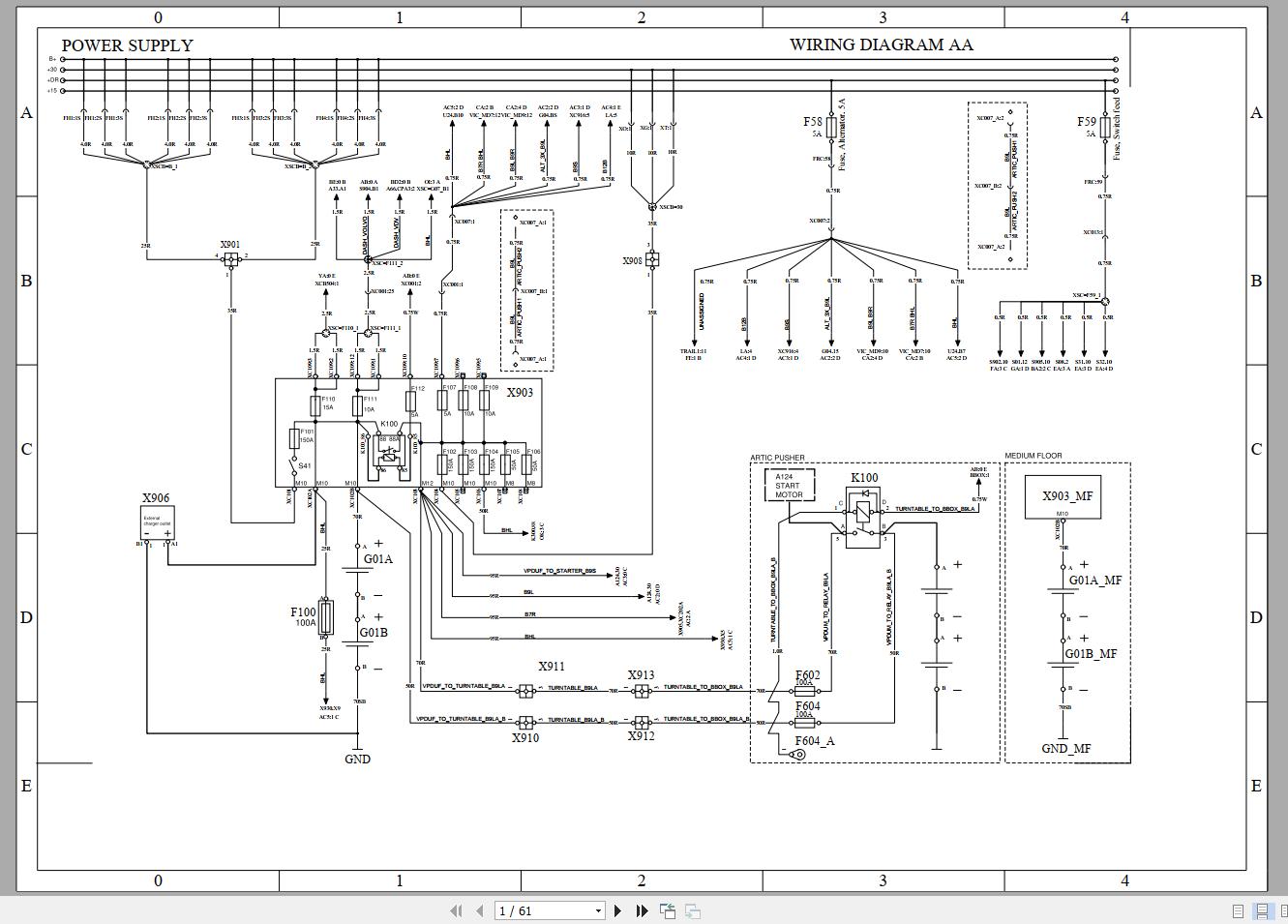
A Volvo truck wiring diagram is essentially a visual roadmap of the entire electrical system. It's a detailed schematic representation showing all the wires, connectors, sensors, relays, fuses, and electronic control units (ECUs) – also sometimes referred to as modules – and how they are interconnected. Its primary purposes are:
- Troubleshooting Electrical Faults: When a component fails, a wiring diagram helps you trace the circuit back to its source, identifying potential breaks, shorts, or faulty connections.
- Performing Repairs: The diagram shows the correct wiring configuration, ensuring you reconnect components accurately after a repair or replacement.
- Adding or Modifying Circuits: If you plan to add aftermarket accessories, like lights or a CB radio, a wiring diagram helps you tap into the appropriate circuits safely and correctly.
- Understanding System Operation: Even if you aren't actively working on the electrical system, studying the diagram can provide a deeper understanding of how different components interact and how the overall system functions.
- Preventative Maintenance: Understanding the wiring and where common issues may exist can help you prevent further more costly repairs.
Key Specs and Main Parts of a Volvo Truck Wiring Diagram
Volvo truck wiring diagrams are model-specific, meaning a diagram for a Volvo FH16 will be different from one for a Volvo VNL. They also vary depending on the model year due to design changes and the introduction of new technologies. Some key elements to look for include:
- Power Distribution: The diagram will show the main power source (battery), the starter motor, the alternator, and the power distribution points (fuse boxes, relays).
- Grounding Points: Properly grounded connections are crucial for preventing electrical issues. The diagram identifies all grounding locations.
- ECUs (Electronic Control Units): These computers control various functions, such as the engine (ECU), transmission (TCU), anti-lock braking system (ABS), and body control module (BCM). The diagram shows how these ECUs are wired and communicate with each other.
- Sensors: Numerous sensors monitor parameters like temperature, pressure, speed, and position. The diagram illustrates where these sensors are located and how they are connected to the appropriate ECUs.
- Actuators: Actuators, such as solenoids, motors, and relays, control various functions based on signals from the ECUs. The diagram shows how these actuators are powered and controlled.
- Connectors: Wiring diagrams meticulously detail the types and locations of various connectors throughout the vehicle. This information is critical for testing voltage, continuity, and resistance.
Decoding the Diagram: Symbols, Lines, Colors, and Icons
Understanding the symbols and conventions used in a wiring diagram is essential for accurate interpretation. Here's a breakdown of some common elements:
- Lines: Solid lines represent wires, and their thickness might sometimes (but not always) indicate wire gauge. Dotted lines often indicate shielded wires or data communication buses (like CAN bus).
- Colors: Each wire is assigned a color code. A legend on the diagram will explain these codes (e.g., RD = Red, BK = Black, WH = White). Color coding is crucial for identifying the correct wire in a harness.
- Symbols: Various symbols represent electrical components. Some common examples include:
- Resistor: A zig-zag line.
- Capacitor: Two parallel lines.
- Diode: A triangle pointing towards a line.
- Relay: A coil symbol with associated switch contacts.
- Fuse: A squiggly line inside a rectangle.
- Ground: A series of horizontal lines, decreasing in length.
- Icons: Icons represent specific components, such as headlights, taillights, motors, and sensors. These icons are usually simplified representations of the actual components.
- Numerical Codes: Each wire and connector often has a numerical code associated with it. These codes help you identify the specific wire or connector on the physical vehicle and cross-reference it with the diagram.
How It Works: Tracing a Circuit
To effectively use a wiring diagram, you need to understand how to trace a circuit. Start by identifying the component you're interested in. Locate its symbol or icon on the diagram. Then, follow the wires connected to that component. Pay attention to the color codes and numerical codes. The diagram will show you where the wires lead – to a power source, a ground, another component, or an ECU. By following the circuit step-by-step, you can understand how the component receives power, how it is controlled, and how it interacts with other parts of the system. Imagine a circuit for a headlight. It begins at the battery, flows through a fuse, a switch, then the headlight itself, and finally to a ground. The wiring diagram lays out this entire pathway visually.
Real-World Use: Basic Troubleshooting Tips
Here are some basic troubleshooting tips using a Volvo truck wiring diagram:
- No Power: If a component isn't working, check the wiring diagram to identify the power source and any fuses or relays in the circuit. Use a multimeter to check for voltage at the component and at various points along the circuit.
- Short Circuit: If a fuse keeps blowing, there's likely a short circuit. The wiring diagram can help you identify potential areas where the wire might be grounding out (rubbing against the chassis, for example).
- Open Circuit: If a wire is broken or a connector is disconnected, the circuit is open. Use a multimeter to check for continuity along the circuit to identify the break.
- Sensor Problems: If a sensor is malfunctioning, the wiring diagram can help you check the sensor's wiring and connections to the ECU. You can also use the diagram to identify the correct wires for testing the sensor's voltage or resistance.
- Communication Issues: If there are issues with communication between modules, the wiring diagram can help trace the CAN bus wires and check for shorts, opens, or termination resistor problems.
Safety First: Identifying Risky Components
Working with electrical systems involves inherent risks. Always disconnect the battery's negative terminal before working on any electrical component. Be particularly cautious around these components:
- High-Voltage Circuits: Some systems, like the ignition system or hybrid systems, use high voltages that can be lethal. Always follow proper safety procedures when working around these circuits.
- Airbag System: The airbag system is sensitive and can deploy unexpectedly if not handled correctly. Consult the service manual for specific instructions on disabling the airbag system before working on it.
- Fuel Injection System: Incorrectly handling fuel injectors or fuel lines can create a fire hazard. Always relieve fuel pressure before disconnecting any fuel lines.
- Batteries: Batteries contain corrosive acid and can produce explosive gases. Wear appropriate protective gear (gloves, eye protection) and ensure proper ventilation when working with batteries.
By understanding the purpose, components, and symbols of a Volvo truck wiring diagram, you can effectively troubleshoot and repair electrical problems on your vehicle. Always prioritize safety and consult the service manual for specific procedures and precautions.
We have the files you need, and you can download the correct wiring diagram specific to your Volvo truck model now by clicking on the following link (link to download here). Please provide the year and model of your truck to ensure you get the correct diagram.