
Vw 3 Wire Crank Sensor Wiring Diagram
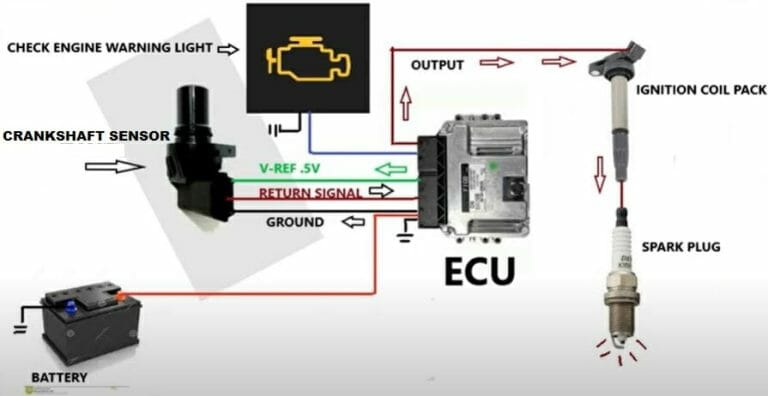
Let's dive into the world of Volkswagen's 3-wire Crankshaft Position (CKP) sensor wiring. If you're a seasoned DIY mechanic, a car modder, or simply an intermediate car owner looking to deepen your understanding, this article will equip you with the knowledge to interpret and utilize a VW 3-wire crank sensor wiring diagram. We'll break down the purpose, key components, symbols, functionality, real-world applications, and safety considerations. Having a solid grasp of this diagram is crucial for troubleshooting engine problems, performing repairs, and even understanding engine management system modifications.
Why Understand the CKP Sensor Wiring Diagram?
The crankshaft position sensor is a critical component in your engine's timing system. It tells the Engine Control Unit (ECU) the exact position and rotational speed of the crankshaft. This information is vital for determining when to fire the spark plugs and inject fuel. A faulty CKP sensor or wiring issue can lead to a variety of problems, including:
- No-start conditions: If the ECU doesn't know the crank position, it won't initiate the spark and fuel injection sequence.
- Rough running: Inaccurate timing can cause misfires and poor engine performance.
- Stalling: An intermittent signal from the CKP sensor can cause the engine to stall unexpectedly.
- Check Engine Light (CEL): A fault in the CKP sensor circuit will often trigger a CEL.
Understanding the wiring diagram allows you to diagnose these issues effectively. You can trace circuits, check for voltage, ground, and continuity, and identify potential problems such as short circuits, open circuits, and damaged wiring.
Key Specs and Main Parts
Before we delve into the diagram, let's define some key specifications and components:
- Crankshaft Position (CKP) Sensor: This is the sensor itself, responsible for detecting the crankshaft's position. VW typically uses a hall-effect sensor.
- ECU (Engine Control Unit): The "brain" of the engine, it receives data from the CKP sensor and controls fuel injection and ignition.
- Wiring Harness: The bundle of wires that connect the CKP sensor to the ECU and other components.
- Connectors: The plugs that connect the CKP sensor to the wiring harness.
A typical 3-wire CKP sensor has the following connections:
- Power Supply (Usually 5V): Provides power to the sensor. This is a stable, regulated voltage.
- Ground: Provides a return path for the electrical current.
- Signal Wire: Carries the information about the crankshaft's position back to the ECU. The signal is usually a pulse wave.
Decoding the Symbols in the Diagram
A wiring diagram is a symbolic representation of the electrical circuit. Understanding these symbols is key to interpreting the diagram correctly.
- Lines: Represent wires. Thicker lines may indicate larger gauge wires.
- Colors: Each wire is assigned a specific color, which is noted on the diagram. Common colors include Red (power), Black (ground), and various colors for signal wires. Color codes help to identify specific wires within the harness.
- Squares/Rectangles: Often represent components like the ECU or relays.
- Circles: May represent fuses or other smaller components.
- Ground Symbol: A series of descending lines or a triangle pointing downwards, indicating a connection to ground.
- Connectors: Usually depicted as interlocking shapes, representing the physical connectors that join wires. These will also have pin numbers associated with them.
The diagram will also include alphanumeric codes that identify each wire and component. For instance, you might see "T6a/3," which means connector "T6a," pin number 3. Referencing these codes against the physical connectors is critical for accurate diagnosis.
How It Works: From Crankshaft to ECU
The CKP sensor is typically mounted near the crankshaft pulley or flywheel. It works by sensing the passing of teeth or notches on a reluctor wheel (also called a tone wheel) attached to the crankshaft. As the crankshaft rotates, the reluctor wheel's teeth interrupt a magnetic field within the sensor, creating a pulsed voltage signal. This is based on the principle of electromagnetic induction (specifically, Faraday's Law). In the case of a hall-effect sensor, it senses the change in the magnetic field directly using the Hall effect.
The frequency and pattern of these pulses are directly proportional to the crankshaft's speed and position. The signal wire carries this information to the ECU. The ECU interprets the signal and uses it to calculate the precise timing for ignition and fuel injection. Without this crucial input, the engine wouldn't be able to function properly.
Think of it like this: the CKP sensor is the eyes of the engine management system, providing critical visual information that the ECU uses to make decisions.
Real-World Use: Troubleshooting Tips
Let's put this knowledge into practice. Suppose your VW won't start, and you suspect a CKP sensor issue. Here's how you can use the wiring diagram:
- Locate the CKP sensor connector: Use the diagram to find the connector location. The diagram will show you what it looks like and where it’s located on the engine.
- Check for power and ground: Using a multimeter, verify that the power supply wire (typically 5V) is receiving the correct voltage with the ignition on. Also, check the ground wire for continuity to ground. A bad ground is a common culprit.
- Inspect the signal wire: With the engine cranking (or using a scan tool to simulate cranking), check the signal wire for a fluctuating voltage. A scope is ideal, but a multimeter can often indicate if the signal is being produced at all.
- Check for continuity: Use the diagram to trace the wiring from the CKP sensor to the ECU. Use a multimeter to check for continuity (a complete circuit) between these points. Also, check for shorts to ground – there should be no continuity between the signal wire and ground.
- Inspect the wiring and connectors: Look for any signs of damage, such as frayed wires, corroded connectors, or loose connections.
If you find a problem, don't just replace the sensor immediately. A wiring issue can often mimic a faulty sensor. Correcting the wiring problem will save you money and prevent future issues.
Safety First!
Working with electrical systems can be dangerous. Always follow these safety precautions:
- Disconnect the battery: Before working on any electrical component, disconnect the negative battery cable to prevent short circuits and electrical shocks.
- Use caution when working near the fuel system: Fuel is highly flammable. Avoid sparks or open flames when working near fuel lines or injectors.
- Be aware of hot surfaces: The engine can get very hot. Avoid touching hot components, such as the exhaust manifold.
- Use proper tools: Use insulated tools designed for automotive electrical work.
- Never probe wires without understanding the circuit: Incorrect probing can damage the ECU or other components. Refer to the wiring diagram to understand the circuit before testing.
- Exercise extra caution when testing the ignition system. High voltages are present.
Conclusion
Understanding the VW 3-wire crank sensor wiring diagram empowers you to diagnose and repair engine problems effectively. By grasping the purpose, components, symbols, and functionality of the circuit, you can troubleshoot issues systematically and confidently. Remember to prioritize safety and use the diagram as your guide. With this knowledge, you're well-equipped to tackle CKP sensor-related problems on your VW.
We have the wiring diagram available for download. With the right information, you can diagnose and fix your car with confidence! This is just one tool to help you.