Water Pressure Switch Wiring Diagram
Understanding a water pressure switch wiring diagram is crucial for a variety of reasons. Whether you're diagnosing a well pump issue, customizing a water-cooled PC build, or even delving into the plumbing system of an RV, accurately interpreting these diagrams can save you time, money, and potential headaches. This article breaks down the intricacies of water pressure switch wiring diagrams, providing you with the knowledge to confidently tackle related repairs and modifications.
Why This Diagram Matters
The primary purpose of understanding a water pressure switch wiring diagram is to facilitate informed troubleshooting and repair. These diagrams serve as a visual roadmap of the electrical connections within a water pressure system. They are invaluable for:
- Diagnosing Malfunctions: Identifying faulty components or wiring breaks by tracing the circuit.
- Performing Repairs: Ensuring correct re-wiring after replacing a switch, pump, or other part.
- Making Modifications: Safely adding components or altering the system for customized applications.
- Understanding System Logic: Gaining a deeper understanding of how the system works as a whole.
Key Specs and Main Parts
Before diving into the diagram itself, it's important to familiarize yourself with the key components involved in a typical water pressure system. This will aid in understanding the diagram's representation of these parts.
Essential Components:
- Water Pressure Switch: The brain of the system, this device monitors water pressure and activates or deactivates the pump to maintain a desired pressure range.
- Well Pump (or other water source pump): The workhorse that draws water from the source (well, tank, etc.) and delivers it to the system.
- Pressure Tank: A reservoir that stores water under pressure, reducing pump cycling and providing a consistent water supply.
- Power Source: Typically 120V or 240V AC, depending on the pump's requirements.
- Wiring: Cables connecting all components, typically using standard wire colors (e.g., black for hot, white for neutral, green for ground).
- Circuit Breaker: A safety device that protects the circuit from overloads and short circuits.
- Control Box (optional): Some pumps, especially submersible well pumps, use a control box that houses capacitors and relays to assist with starting and running the pump.
Key Specifications to Note:
- Voltage: The operating voltage of the system (e.g., 120V, 240V).
- Amperage: The current draw of the pump. Ensure the wiring and circuit breaker are appropriately sized.
- Pressure Settings: The cut-in (turn-on) and cut-out (turn-off) pressure settings of the switch. For example, a 40/60 switch turns on at 40 PSI and turns off at 60 PSI.
- Wire Gauge: The thickness of the wires. Thicker wires can handle more current.
Understanding the Symbols
A water pressure switch wiring diagram uses standardized symbols to represent different components and connections. Knowing these symbols is essential for interpreting the diagram accurately.
- Lines: Solid lines represent wires connecting components. Dashed lines may represent control signals or less critical connections.
- Colors: Wire colors are usually indicated on the diagram (e.g., BLK for black, WHT for white, GRN for green). Standard color coding is crucial for proper wiring.
- Switch Symbol: The water pressure switch is typically represented by a symbol resembling a mechanical switch, with terminals labeled for line voltage in (L1, L2) and load voltage out (T1, T2) to the pump. Sometimes, a diagram will show a simplified switch with just two terminals.
- Motor Symbol: The well pump motor is represented by a circle with an "M" inside or a more detailed representation of a motor winding.
- Ground Symbol: A three-tiered symbol indicates the ground connection. All metal components should be grounded for safety.
- Junctions: Dots where lines intersect indicate a connection. Lines crossing without a dot indicate no connection.
- Circuit Breaker Symbol: A small rectangle with a curved line inside representing a switch.
Important note about line voltage: In a 240V system, you'll often see two hot wires (L1 and L2). These wires carry opposite phases of the AC voltage. In a 120V system, you'll typically have one hot wire (L1) and a neutral wire.
How It Works: Following the Circuit
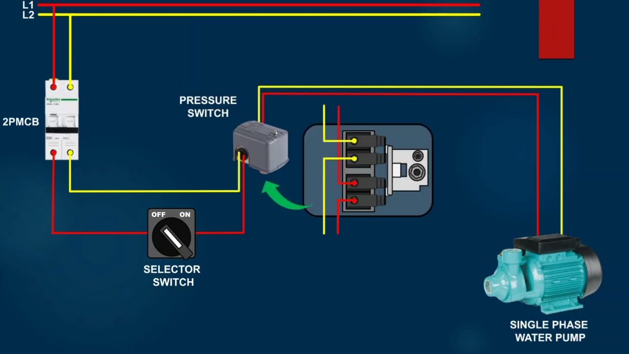
A typical water pressure switch wiring diagram shows the following basic circuit:
- Power Source: The circuit begins at the power source (circuit breaker panel).
- Hot Wire to Switch: A hot wire (typically black) runs from the circuit breaker to one terminal (L1) on the water pressure switch. In a 240V system, two hot wires (L1 and L2) will go to the switch.
- Switch Operation: When the water pressure drops below the cut-in pressure, the switch closes, completing the circuit. When the water pressure rises above the cut-out pressure, the switch opens, breaking the circuit.
- Hot Wire to Pump: A hot wire runs from the other terminal (T1) on the water pressure switch to the pump motor. Again, in a 240V system, a second hot wire runs from (T2) to the pump.
- Neutral Wire: A neutral wire (typically white) runs directly from the circuit breaker panel to the pump motor.
- Ground Wire: A ground wire (typically green or bare) connects the pump motor, pressure switch, and other metal components to the ground bus bar in the circuit breaker panel. This is a *critical* safety feature.
The pressure switch acts as a gatekeeper. When the pressure is low, it opens the gate (closes the circuit) allowing electricity to flow to the pump, which then runs. When the pressure reaches the set limit, it closes the gate (opens the circuit) cutting off power to the pump.
Real-World Use: Basic Troubleshooting Tips
Here are some basic troubleshooting tips using a water pressure switch wiring diagram as a guide:
- Pump Not Running:
- Check Power: Verify the circuit breaker is not tripped.
- Check Switch: Use a multimeter to test for voltage at the switch terminals. If voltage is present on the input side (L1), but not on the output side (T1) when the pressure is low, the switch may be faulty.
- Check Wiring: Inspect all wiring connections for looseness or corrosion.
- Check Pump Motor: If voltage is present at the pump motor but the pump isn't running, the motor itself may be faulty.
- Pump Runs Constantly:
- Check Switch: The switch might be stuck in the closed position.
- Check for Leaks: A leak in the system could be causing the pressure to drop continuously, forcing the pump to run.
- Check Well Level: If the well is running dry, the pump will run continuously trying to draw water.
- Rapid Cycling (Pump Turning on and off Frequently):
- Check Pressure Tank: The pressure tank may be waterlogged (lacking air pressure).
- Check for Leaks: Small leaks can cause rapid pressure fluctuations.
Use a multimeter: A multimeter is an essential tool for electrical troubleshooting. It allows you to measure voltage, current, and resistance, helping you pinpoint the source of the problem.
Safety First! Handling Risky Components
Working with electricity can be dangerous. Always take the following precautions:
- Disconnect Power: Always disconnect the power at the circuit breaker before working on any electrical components. This is non-negotiable.
- Use Insulated Tools: Use tools with insulated handles to protect yourself from electric shock.
- Test for Voltage: Even after disconnecting the power, use a voltage tester to verify that the circuit is de-energized.
- Grounding: Ensure all metal components are properly grounded.
- When in doubt, call an electrician: If you are not comfortable working with electricity, hire a qualified electrician.
- Wet Conditions: Never work with electrical components in wet conditions. Water is an excellent conductor of electricity.
Capacitors hold charge: Control boxes for submersible pumps often contain capacitors. These can hold a dangerous charge even after the power is disconnected. Discharge capacitors using a resistor before handling them.
We have the water pressure switch wiring diagram file. You can download the diagram and start your work!