Well Pump Control Box Wiring Diagram
So, you're diving into the world of well pump control boxes, huh? Good for you. Understanding these little guys is crucial for anyone dealing with a well water system, whether you're fixing a problem, upgrading components, or just trying to get a better handle on how your home works. This article breaks down the wiring diagram of a typical well pump control box. Think of it as a roadmap to keeping your water flowing. We’re going to cover the purpose of the diagram, the key components it represents, how it all works, some real-world troubleshooting tips, and most importantly, the safety precautions you need to take when working with electricity.
Purpose of the Well Pump Control Box Wiring Diagram
Why bother with a wiring diagram? Well, several reasons. First and foremost, it's your lifeline when troubleshooting. When your well pump suddenly decides to take a vacation, the control box is often the first place to look. The diagram helps you trace circuits, identify potential faults, and verify connections. Trying to diagnose a problem without it is like navigating a maze blindfolded.
Secondly, the diagram is invaluable for repairs and replacements. If you need to replace a capacitor, relay, or even the entire control box, the diagram ensures you wire everything correctly. Incorrect wiring can lead to pump failure, electrical damage, or even a fire hazard.
Finally, understanding the diagram helps you learn the system. Even if you don't plan on doing any repairs yourself, knowing how the control box works gives you a better understanding of your well water system and allows you to communicate more effectively with professionals. It empowers you to ask the right questions and make informed decisions about maintenance and upgrades.
Key Specs and Main Parts
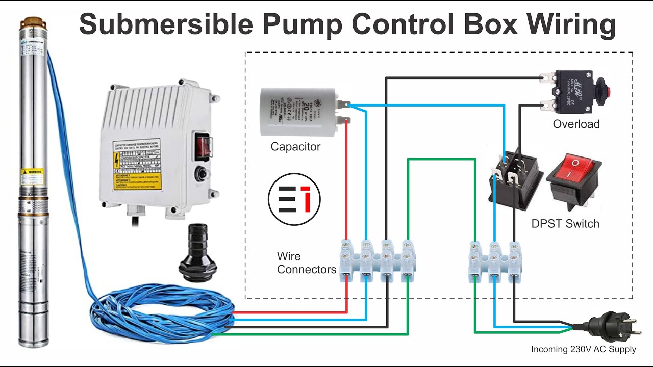
Before we dissect the diagram, let's identify the main components typically found within a well pump control box. Keep in mind that specifics vary by pump type (e.g., two-wire vs. three-wire) and horsepower rating, so always refer to the specific diagram for your setup. Here are the common elements:
- Line Voltage Input (L1, L2): This is where the power from your breaker panel enters the control box. Typically 220V or 240V in the US for larger pumps.
- Motor Start Capacitor: This capacitor provides a jolt of energy to help the motor start. It's usually a high-capacitance, non-polarized capacitor.
- Motor Run Capacitor: This capacitor helps the motor run efficiently once it's started. Usually a lower capacitance than the start capacitor.
- Relay (or Contactor): This is an electrically operated switch that controls the power to the pump motor. It's triggered by the pressure switch.
- Overload Protection (Heater): A thermal overload protector designed to cut power if the motor draws too much current. This prevents the motor from overheating and burning out.
- Terminal Blocks: These are used to connect wires to various components within the control box. They provide a secure and organized connection point.
- Pressure Switch Connections: Connections for the pressure switch, which senses the water pressure in your system and turns the pump on and off accordingly.
- Ground Connection: An essential safety feature that provides a path for fault current to return to the source, tripping the breaker and preventing electrical shock.
Understanding Wiring Diagram Symbols
The wiring diagram is a symbolic representation of the electrical connections. Here’s a breakdown of common symbols:
- Solid Lines: Represent wires. The thickness of the line doesn't usually indicate wire gauge, but it’s good practice to use the correct gauge wire for the amperage your pump requires.
- Dotted Lines: Sometimes used to indicate connections on the back of a component or a wire that runs behind other components.
- Circles: Can represent various components, such as terminal blocks or junction points. Often have a letter or number inside to identify them.
- Capacitor Symbol: Two parallel lines, either straight (non-polarized) or one curved and one straight (polarized). Well pump control boxes use non-polarized capacitors.
- Relay Coil Symbol: Usually a coil or looped symbol. This represents the coil of the relay, which is energized to close the relay contacts.
- Relay Contact Symbol: Two straight lines, either normally open (NO) or normally closed (NC). The contacts switch states when the relay coil is energized.
- Resistor Symbol: A zigzag line. In a control box, this is likely part of the overload protection circuit (heater element).
- Color Codes: Wires are often color-coded to help with identification. Common colors include Black (hot), White (neutral), Green (ground), Red (another hot or a control wire), and Blue (often a control wire). Always verify color codes with your diagram as conventions may vary.
How It Works: A Step-by-Step Explanation
Let's trace the flow of electricity through a simplified well pump control box circuit. We'll assume a 240V system.
- Power In: 240V power enters the control box from your breaker panel via L1 and L2.
- Pressure Switch: The power then runs to the pressure switch. When the water pressure in your tank drops below a set threshold (e.g., 40 PSI), the pressure switch closes, completing the circuit.
- Relay Activation: The closed pressure switch energizes the relay coil.
- Relay Contacts Close: When the relay coil is energized, its contacts close, allowing power to flow to the pump motor.
- Capacitor Assist: The start capacitor, in conjunction with a centrifugal switch inside the motor (or sometimes an electronic switch), provides a high-current boost to get the motor spinning. Once the motor reaches a certain speed, the centrifugal switch opens, disconnecting the start capacitor from the circuit. The run capacitor remains in the circuit to improve motor efficiency.
- Motor Operation: The pump motor spins, drawing water from the well and filling your pressure tank.
- Pressure Reached: Once the water pressure reaches the upper limit set on the pressure switch (e.g., 60 PSI), the pressure switch opens, de-energizing the relay coil.
- Pump Stops: The relay contacts open, cutting power to the pump motor, and the cycle repeats.
- Overload Protection: If the motor draws excessive current due to a problem (e.g., a blockage in the pump), the overload protector (heater) heats up and trips, opening a circuit and shutting down the pump to prevent damage.
Real-World Use: Basic Troubleshooting Tips
Here are a few basic troubleshooting tips using your wiring diagram:
- Pump Not Running: Check the breaker first! Then, use a multimeter to check for voltage at the line voltage input terminals (L1 and L2) inside the control box. If there's voltage there, check if the pressure switch is closed. If the pressure switch is closed and there's still no power to the pump, suspect a faulty relay or wiring issue.
- Pump Hums But Doesn't Start: This often indicates a faulty start capacitor. Use the wiring diagram to locate the capacitor and test it with a capacitance meter. Also, check the motor windings for shorts or opens using an ohmmeter.
- Pump Runs But Doesn't Build Pressure: This is usually a pump issue (e.g., a worn impeller) and not directly related to the control box. However, ensure the pump is receiving the correct voltage and amperage as indicated on the motor nameplate.
- Pump Runs Constantly: This could be a leak in your system, a faulty pressure switch, or a stuck relay. Check the pressure switch first.
Safety First!
Working with electrical circuits can be extremely dangerous. Always disconnect power to the control box at the breaker before doing any work. Verify the absence of voltage with a multimeter before touching any wires. Be particularly careful around the capacitors. These can store a lethal charge even after the power is disconnected. Discharge them with a resistor before handling them. If you're not comfortable working with electricity, hire a qualified electrician or well pump technician.
The capacitors in the control box can hold a dangerous electrical charge even after the power is disconnected. It’s crucial to discharge them before handling them. Using an insulated screwdriver with a resistor, carefully short the capacitor terminals to discharge any stored energy.
Finally, never bypass safety devices like the overload protector. These are in place to protect your pump motor and prevent fires.
We have a detailed, downloadable wiring diagram available for you. This diagram will provide a visual reference for all the components and connections discussed in this article. With this resource and the knowledge you’ve gained, you’ll be well-equipped to troubleshoot and maintain your well pump control box effectively.