
Wiring A Trailer With Electric Brakes
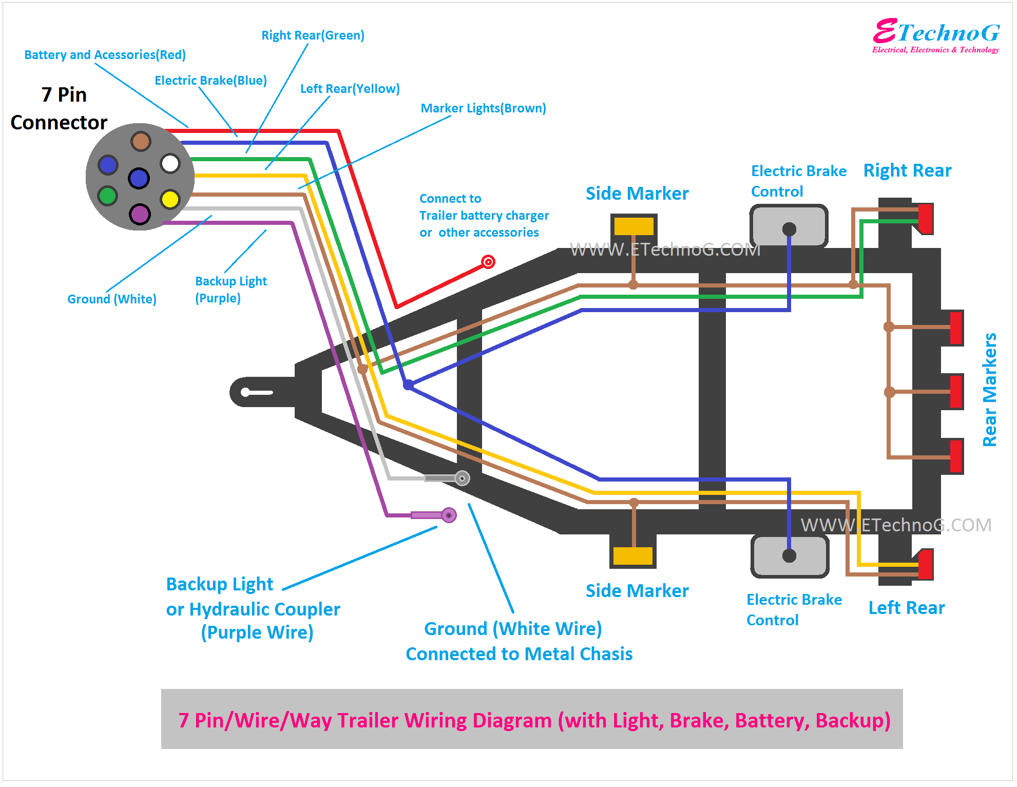
So, you're looking to wire up a trailer with electric brakes. Good choice! Electric brakes are a significant upgrade for heavier trailers, providing much better stopping power and control. This article provides a detailed guide, walking you through the process step-by-step. Whether you're doing a complete rewire, diagnosing a problem, or just expanding your knowledge, understanding trailer wiring, especially for electric brakes, is essential for safe towing.
Why This Matters: Towing Safety and Wiring Basics
Proper trailer wiring is absolutely critical for safety. Faulty wiring can lead to brake failure, malfunctioning lights, or even electrical fires. This guide provides a comprehensive overview, including wiring diagrams and troubleshooting tips, allowing you to confidently tackle this project. We'll cover the key components, wiring standards, and troubleshooting techniques so you can properly wire or repair your trailer. We also provide a link to download the full wiring diagram at the end of this article.
Key Specs and Main Parts
Before we dive into the wiring, let's cover the essential components and their specifications. Understanding these parts is crucial for successful troubleshooting and repair.
The 7-Way Connector
The 7-way RV blade connector is the most common type used for trailers with electric brakes. It provides connections for all necessary functions: tail lights, stop lights, turn signals, running lights, reverse lights, electric brakes, and a 12V power supply (often for charging a trailer battery). While other connectors exist (4-way flat, 5-way flat, 6-way round), we will focus on the 7-way, as it is required for electric brakes.
Brake Controller
The brake controller, mounted inside your tow vehicle, is the brains of the electric brake system. It senses when you're braking and sends a proportional amount of current to the trailer brakes, based on the gain and sensitivity settings. Brake controllers can be either time-delayed or proportional. Proportional controllers are generally preferred as they apply the trailer brakes in direct relation to how hard the tow vehicle is braking, providing smoother and more responsive stopping power.
Electric Brake Assemblies
Located inside the trailer's brake drums, the electric brake assemblies consist of an electromagnet, brake shoes, and associated hardware. When current is applied, the electromagnet is energized, pulling it against the brake drum. This action activates the brake shoes, slowing the trailer wheels.
Wiring Gauge
Using the correct wiring gauge (thickness) is essential to handle the current draw of the electric brakes. Generally, 12-gauge wire is recommended for the brake circuit, but 10-gauge is often preferred for longer trailers to minimize voltage drop. For lighting circuits, 16-gauge wire is usually sufficient. Consult your brake controller and brake assembly documentation for specific current requirements and wire gauge recommendations.
Junction Box
A junction box located on the trailer’s A-frame (tongue) provides a central point to connect all the wires. This keeps the wiring tidy and protected from the elements.
Understanding Wiring Symbols and Conventions
Wiring diagrams use standard symbols to represent components and connections. Here's a breakdown of common symbols you'll encounter:
- Solid Line: Represents a wire.
- Dotted Line: May represent a ground connection or a wire running behind other components.
- Circles: Typically represent connectors or junction points.
- Resistor Symbol (Zigzag Line): Represents a resistor or, in some diagrams, the brake magnet coil.
- Ground Symbol (Downward-pointing pyramid): Indicates a connection to the chassis ground.
Color Coding: Standard color codes help identify the function of each wire. While not universally enforced, the following is a common convention:
- White: Ground. Absolutely critical for all circuits.
- Black: 12V Power Supply (Auxiliary power/charging circuit).
- Blue: Electric Brakes.
- Brown: Tail/Running Lights.
- Yellow: Left Turn/Stop Light.
- Green: Right Turn/Stop Light.
- Red: Auxiliary Function (often reverse lights).
How It Works: The Electric Brake System
The electric brake system is relatively straightforward. When you apply the brakes in your tow vehicle, the brake controller sends a signal to the electric brake assemblies on the trailer. This signal energizes the electromagnets within the brake assemblies. The energized electromagnet is drawn towards the rotating brake drum. This movement forces the brake shoes against the drum, creating friction and slowing the trailer's wheels. The amount of braking force is proportional to the current supplied by the brake controller, which is in turn determined by the deceleration of the tow vehicle (in the case of proportional controllers) or a pre-set time delay (in the case of time-delayed controllers). The white wire completes the circuit, providing the necessary ground for the brake electromagnets.
Real-World Use: Basic Troubleshooting
Even with careful wiring, problems can arise. Here are some common issues and troubleshooting tips:
- No Brakes: Check the brake controller fuse in the tow vehicle. Inspect the trailer wiring for loose connections or damage, especially around the axles where wires can be snagged. Use a multimeter to test for voltage at the brake magnets when the brake pedal is pressed. Verify the trailer ground connection is clean and secure.
- Weak Brakes: Adjust the gain setting on the brake controller. Inspect the brake drums and shoes for wear or contamination (grease, oil). Adjust the brake shoes for proper clearance.
- Brakes Lock Up: Lower the gain setting on the brake controller. Check the brake magnets for damage or excessive rust buildup. Ensure the brake controller is compatible with your trailer's brake system (some controllers are not compatible with certain types of electric brake actuators).
- Lights Not Working: Check the bulbs. Inspect the wiring for breaks or shorts. Clean the contacts in the 7-way connector. Use a test light to verify voltage at each pin of the 7-way connector.
Always disconnect the trailer from the tow vehicle before performing any electrical repairs.
Safety: Handle with Care
Working with electrical systems always presents risks. Remember these safety precautions:
- Disconnect the Battery: Always disconnect the negative battery terminal in both the tow vehicle and the trailer before working on any electrical wiring. This prevents accidental shorts and potential electrical shocks.
- Fuses are Crucial: Use properly sized fuses to protect the wiring and components. Never bypass a fuse with a wire or other conductive material.
- Wiring Protection: Protect wiring from abrasion and heat. Use conduit or loom to shield wires from sharp edges and exhaust components.
- Water Intrusion: Protect wiring connections from moisture. Use weatherproof connectors or apply dielectric grease to prevent corrosion.
- Brake Controller Installation: Follow the brake controller manufacturer's instructions carefully. Improper installation can result in brake failure or damage to the controller.
Brake magnets are a high resistance load and will draw significant current. Be very careful when testing or troubleshooting the brake circuit as short circuits here can cause serious damage. Always wear appropriate safety glasses and gloves when working on electrical systems. If you are not comfortable working with electrical wiring, consult a qualified technician.
By following this guide, you can confidently tackle wiring or troubleshooting the electric brakes on your trailer. Remember to take your time, double-check your connections, and prioritize safety.
We have the full trailer wiring diagram available for download. Click here to download the diagram.