
Wiring Air Compressor Pressure Switch
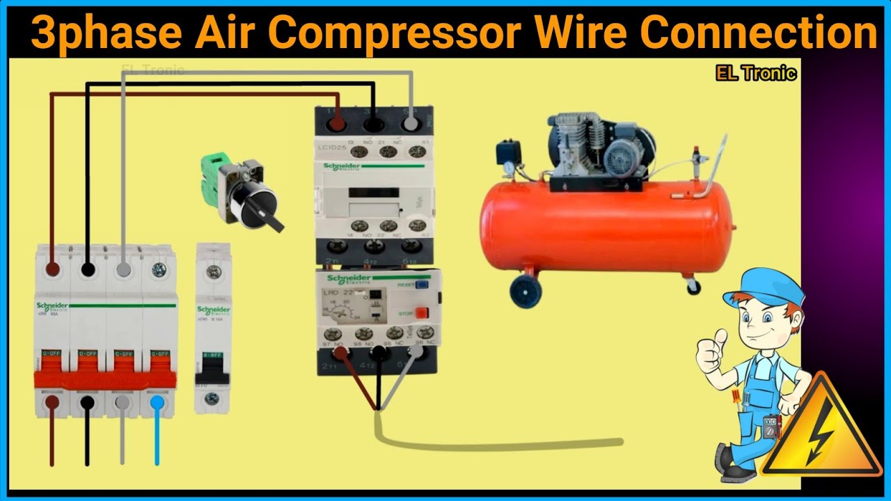
So, you're tackling the wiring of an air compressor pressure switch? Whether you're replacing a faulty one, upgrading your system, or just learning the ropes of pneumatic systems, understanding the wiring is crucial. This guide aims to demystify the process, giving you the knowledge to confidently handle this task. We'll break down the components, explain the wiring diagram, and offer some real-world troubleshooting tips. Plus, we've got a downloadable wiring diagram available for you to refer to.
Why Understanding Pressure Switch Wiring Matters
Wiring a pressure switch isn't just about connecting wires. It's about ensuring your air compressor operates safely and efficiently. Incorrect wiring can lead to a host of problems, from a compressor that won't turn on to one that runs continuously, potentially causing damage to the motor or even posing a safety hazard. Understanding the wiring diagram allows you to:
- Diagnose problems: Quickly identify wiring issues when your compressor malfunctions.
- Perform repairs: Replace a faulty switch with confidence, knowing you're wiring it correctly.
- Upgrade your system: Integrate a new pressure switch with different features or pressure ratings.
- Expand your knowledge: Gain a deeper understanding of how pneumatic systems operate.
Key Specs and Main Parts of a Pressure Switch System
Before we dive into the wiring, let's identify the key components and specifications you'll encounter:
Main Parts:
- Pressure Switch: The heart of the system. This device monitors the air pressure in the tank and activates or deactivates the compressor motor accordingly. It typically has terminals for power input and output to the motor.
- Motor Starter (Optional): For larger compressors (typically over 5HP), a motor starter is used to handle the high amperage draw of the motor. The pressure switch controls the motor starter, which in turn controls the motor.
- Air Compressor Motor: The electric motor that drives the compressor pump.
- Power Source: Typically 120V or 240V AC, depending on the size of the compressor.
- Tank Pressure Gauge: Shows the current pressure within the air tank.
- Unloader Valve: Releases pressure from the compressor head when the motor stops, making it easier to start again.
- Check Valve: Prevents compressed air from flowing back into the compressor pump when it's not running.
Key Specifications:
- Voltage Rating: The voltage the switch is designed to handle (e.g., 120V, 240V). Incorrect voltage can damage the switch or the connected equipment.
- Amperage Rating: The maximum current the switch can safely handle. Exceeding this rating can cause the switch to overheat and fail, or even start a fire.
- Pressure Range: The range of pressures the switch can detect and respond to (e.g., 80-120 PSI).
- Cut-In Pressure: The pressure at which the switch turns the compressor motor on.
- Cut-Out Pressure: The pressure at which the switch turns the compressor motor off.
- Number of Poles: Refers to the number of separate circuits the switch can control. Single-pole switches control one circuit, while double-pole switches control two.
Understanding the Wiring Diagram Symbols
Wiring diagrams use standardized symbols to represent electrical components and connections. Here's a breakdown of common symbols you'll encounter in an air compressor pressure switch wiring diagram:
- Lines: Represent wires or conductors. A solid line indicates a direct connection.
- Circles: Can represent various components, depending on what’s inside. Often used for indicating sensors or other control elements.
- Switches: Represented by a line with a break, indicating an open or closed circuit. The type of switch (SPST, SPDT, DPST, DPDT) will determine the number of poles and throws. SPST - Single Pole Single Throw, SPDT - Single Pole Double Throw, DPST - Double Pole Single Throw, DPDT - Double Pole Double Throw.
- Motor: Usually represented by a circle with an 'M' inside.
- Ground: Indicated by a series of horizontal lines, decreasing in size. It provides a return path for electrical current.
- Colors: Wires are often color-coded for easy identification:
- Black: Typically indicates a hot (live) wire.
- White: Typically indicates a neutral wire.
- Green (or Bare): Indicates a ground wire.
Keep in mind that color codes can vary slightly depending on local electrical codes.
How the Pressure Switch Wiring Works
The pressure switch acts as an automatic on/off switch for your air compressor motor. Here's a simplified explanation of how it works:
- Pressure Drops: As you use compressed air, the pressure in the tank decreases.
- Cut-In Pressure Reached: When the pressure drops to the cut-in pressure setting of the switch, the switch closes the circuit.
- Motor Starts: Closing the circuit allows electricity to flow to the compressor motor, causing it to start.
- Tank Fills: The compressor motor runs, pumping air into the tank and increasing the pressure.
- Cut-Out Pressure Reached: When the pressure reaches the cut-out pressure setting of the switch, the switch opens the circuit.
- Motor Stops: Opening the circuit cuts off power to the compressor motor, causing it to stop.
This cycle repeats automatically, maintaining the air pressure in the tank within the desired range.
Real-World Use: Basic Troubleshooting Tips
Here are a few common issues you might encounter and how to troubleshoot them:
- Compressor won't start:
- Check the power supply to the compressor. Is it plugged in? Is the circuit breaker tripped?
- Inspect the pressure switch. Are the contacts clean and making good contact? Use a multimeter to test for continuity when the tank pressure is below the cut-in point.
- Examine the wiring for any loose connections or damaged wires.
- If the motor has a thermal overload protector, make sure it hasn't tripped.
- Compressor runs continuously:
- Check for leaks in the air lines, fittings, or tank.
- Inspect the pressure switch. Is it stuck in the 'on' position?
- If the compressor is equipped with an unloader valve, make sure it's functioning correctly. A malfunctioning unloader valve can cause the compressor to run continuously.
- Compressor starts and stops frequently (short-cycling):
- This can be caused by a small leak, a faulty check valve, or an improperly adjusted pressure switch.
- Check the pressure switch differential. The differential is the difference between the cut-in and cut-out pressure. If the differential is too small, the compressor may short-cycle.
Safety First!
Working with electricity can be dangerous. Always take the following precautions:
- Disconnect Power: Always disconnect the power supply to the air compressor before working on the wiring.
- Verify No Voltage: Use a multimeter to verify that there is no voltage present at the pressure switch terminals.
- Insulate Wires: Ensure all wires are properly insulated to prevent short circuits.
- Use Proper Tools: Use insulated tools designed for electrical work.
- Work in a Dry Area: Never work on electrical components in a wet or damp environment.
- High Voltage Components: Be especially careful around the motor starter and the motor itself, as these components can carry high voltage.
If you are not comfortable working with electricity, consult a qualified electrician.
We hope this guide has given you a solid understanding of air compressor pressure switch wiring. To further assist you, we have a detailed wiring diagram available for download. This diagram provides a visual representation of the wiring connections and can be a valuable tool for troubleshooting and repair. Good luck, and stay safe!