Wiring Diagram Fog Lights With Relay
So, you're looking to add fog lights to your ride, or maybe you're troubleshooting a current setup? Wiring fog lights with a relay is the *right* way to do it, ensuring safe and efficient operation. This article will walk you through a typical wiring diagram, explaining each component and its function. Consider this your definitive guide to understanding and implementing a properly relayed fog light system.
Purpose
Why bother with all this? A relay is the unsung hero of automotive electrical systems. Directly wiring fog lights to a switch can overload the switch and even the car's existing wiring, potentially leading to blown fuses, a melted switch, or even worse – a fire hazard. Using a relay isolates the high-current draw of the fog lights from the low-current switch circuit. This diagram matters for a few crucial reasons:
- Safety: Prevents overloading your vehicle's electrical system.
- Reliability: Ensures consistent power delivery to the fog lights, leading to brighter and more reliable illumination.
- Longevity: Extends the life of your switch by reducing the current flowing through it.
- Flexibility: Allows for custom control configurations, such as wiring the fog lights to only operate when the low beams are on.
- Troubleshooting: Having a clear understanding of the wiring makes diagnosing problems much easier.
Key Specs and Main Parts
Before diving into the diagram itself, let's identify the key components and their specifications:
- Fog Lights: These are the lights themselves. Their wattage (e.g., 55W each) is crucial because it determines the amperage draw and the required relay and fuse ratings.
- Relay: An electromagnetic switch that controls a high-current circuit (the fog lights) using a low-current signal (from the switch). A standard automotive relay is typically a Single Pole Double Throw (SPDT) or Single Pole Single Throw (SPST) relay. We will be using an SPST for simplicity. Most automotive relays are rated for 30-40 amps.
- Switch: A low-current switch used to activate the relay. This can be an aftermarket switch or an existing switch in your vehicle.
- Fuse: A safety device that protects the wiring and components from overcurrent. Select a fuse rated slightly higher than the expected current draw of the fog lights. For example, if your fog lights draw 10 amps total, use a 15 amp fuse.
- Wiring: The gauge of the wire is crucial. Use thicker gauge wire for high-current circuits (fog lights to relay and relay to battery). A general rule of thumb is to use 14-gauge wire for the fog light circuit and 16-18 gauge for the switch circuit.
- Battery: The source of power for the entire system.
- Ground: Provides a return path for the current back to the battery. A good, clean ground connection is essential for proper operation.
Symbols
Understanding the symbols in the wiring diagram is essential for accurate interpretation.
- Solid Lines: Represent wires connecting the components.
- Dashed Lines: May represent optional connections or ground wires.
- Colors: Wires are often color-coded for identification. Common colors include red (power), black (ground), and yellow, blue, or white (signal). Always refer to your vehicle's wiring diagram for specific color codes.
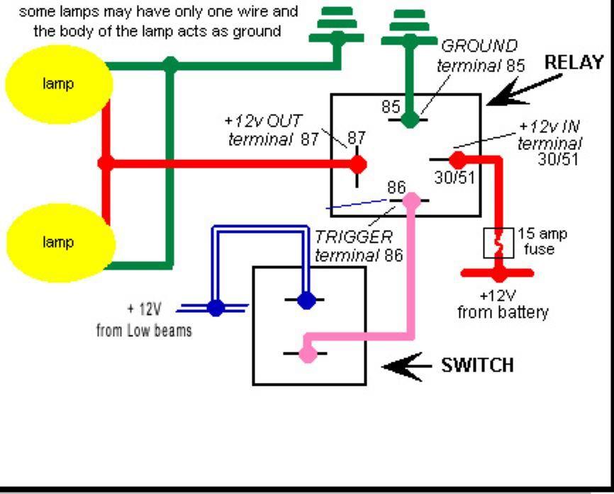
- Relay Symbol: A rectangle with pins labeled 30, 85, 86, and 87 (sometimes 87a if it's an SPDT relay).
- Pin 30: Input power to the relay (from the battery).
- Pin 85: Ground for the relay coil.
- Pin 86: Trigger signal to activate the relay (from the switch).
- Pin 87: Output power to the fog lights.
- Fuse Symbol: A wavy line inside a rectangle.
- Switch Symbol: A line that can be opened or closed to control the flow of current.
- Ground Symbol: A series of lines tapering downwards, indicating a connection to the vehicle's chassis.
How It Works
Here's a breakdown of how the circuit functions:
- Power Source: Power flows from the positive (+) terminal of the battery.
- Fuse Protection: The power first passes through a fuse to protect the circuit from overloads.
- Relay Input: From the fuse, the power goes to Pin 30 of the relay.
- Switch Activation: When you flip the fog light switch, it sends a small amount of current to Pin 86 of the relay. Pin 85 is connected to ground, completing the circuit for the relay's internal coil.
- Relay Activation: Energizing the relay coil creates an electromagnetic field, which pulls a contact inside the relay closed, connecting Pin 30 (power input) to Pin 87 (power output).
- Fog Light Illumination: The power now flows from Pin 87 of the relay to the fog lights.
- Ground Return: The fog lights are grounded to the vehicle's chassis, completing the circuit and allowing them to illuminate.
Real-World Use - Basic Troubleshooting Tips
Even with a perfect diagram and careful wiring, things can go wrong. Here are some common issues and how to diagnose them:
- Fog lights don't turn on at all:
- Check the fuse.
- Verify that the switch is working correctly (use a multimeter to check for continuity when the switch is on).
- Check the ground connections.
- Test the relay by swapping it with a known good relay or using a multimeter to check for continuity across pins 30 and 87 when the relay is activated.
- Check the wiring connections for any loose or corroded terminals.
- Fog lights turn on but are dim:
- Check the ground connections. Poor grounding can cause voltage drop.
- Check the battery voltage.
- Ensure the wiring is the correct gauge. Undersized wiring can cause voltage drop.
- Fuse blows repeatedly:
- Check for a short circuit in the wiring to the fog lights.
- Make sure the fuse is the correct amperage rating.
- Inspect the fog lights themselves for any internal shorts.
- Relay clicks but fog lights don't turn on:
- The relay contacts may be damaged or corroded. Replace the relay.
Safety
Working with automotive electrical systems involves risks. Always prioritize safety:
- Disconnect the Battery: Before starting any electrical work, disconnect the negative (-) terminal of the battery to prevent accidental shorts.
- Proper Tools: Use insulated tools to avoid electrical shocks.
- Proper Wiring: Use the correct gauge wire for the current draw of the fog lights.
- Fuse Protection: Always use a fuse in the circuit to protect against overcurrent.
- Relay Rating: Use a relay with a current rating that exceeds the current draw of the fog lights.
- Avoid Exposed Wires: Ensure all wiring connections are properly insulated to prevent shorts.
- Do not cut corners: Use proper connectors, heat shrink tubing, and cable management techniques. Don't just twist wires together and hope for the best.
Working with the battery and the high-current wiring leading to the relay can be particularly risky. Always double-check your connections and ensure proper insulation to prevent shorts, which can generate significant heat and pose a fire hazard. When in doubt, consult a qualified electrician.
With this comprehensive guide, you're well-equipped to understand and implement a safe and effective fog light wiring system using a relay. Remember to double-check your work, and always prioritize safety. Good luck!