Wiring Diagram For 2 Speed Fan Motor
So, you're looking to dive into the world of 2-speed fan motors, eh? Excellent! Whether you're troubleshooting a malfunctioning cooling system, upgrading your radiator fan for better performance, or just expanding your automotive knowledge, understanding the wiring of these motors is crucial. This article will break down a typical 2-speed fan motor wiring diagram, equipping you with the knowledge to diagnose problems, perform repairs, and even customize your setup with confidence.
Why This Diagram Matters
Think of the wiring diagram as the Rosetta Stone for your car's electrical system. It's a visual map that reveals how each component is connected, allowing you to:
- Diagnose Electrical Faults: Identify shorts, opens, and other wiring issues that can cause your fan to malfunction.
- Perform Repairs Correctly: Ensure you're connecting wires to the right terminals, preventing further damage.
- Understand Fan Control: Learn how the fan speed is regulated, enabling you to modify or upgrade the system.
- Install Aftermarket Components: Integrate new fans or controllers seamlessly into your existing wiring.
- General Knowledge: Broaden your automotive understanding.
Without a clear diagram, you're essentially working blind. You might get lucky, but you're far more likely to create new problems or even damage your car's electrical system.
Key Specs and Main Parts
Before we dive into the diagram itself, let's familiarize ourselves with the key components typically found in a 2-speed fan system:
- Fan Motor: This is the heart of the system. A 2-speed motor has multiple windings (coils of wire) inside, each designed to provide a different speed. The motor usually have three terminals: Ground, Low Speed, High Speed.
- Relays: Electromagnetic switches that control the flow of electricity to the fan motor. They allow a low-current signal from the ECU (Engine Control Unit) or a temperature switch to control a high-current circuit powering the fan. We'll typically find two relays: a Low Speed Relay, and High Speed Relay.
- Fuses: Safety devices that protect the circuit from overcurrent. Always use the correct amperage rating for the fuse. A blown fuse is a sign of a problem that needs to be addressed.
- Temperature Switch or ECU: These components control when the fan turns on and at what speed. A temperature switch is a simple device that closes a circuit when a certain temperature is reached. The ECU, on the other hand, uses sensor data to make more complex decisions about fan speed.
- Wiring Harness: A collection of wires bundled together to connect the various components. Color-coding is used to identify each wire's function.
Typical specifications you might encounter include:
- Voltage: Usually 12V DC in automotive applications.
- Current Draw: The amount of current the fan motor draws at each speed. This is important for selecting the correct fuses and relays.
- Wire Gauge: The thickness of the wires, which must be sufficient to handle the current draw. Heavier gauge wire can carry more current.
Decoding the Diagram: Symbols, Lines, and Colors
A wiring diagram uses standardized symbols and conventions to represent the various components and connections. Here's a breakdown of common elements:
- Lines: Represent wires. The thickness of the line doesn't usually indicate wire gauge, but simply serves to separate the lines from each other for ease of reading.
- Colors: Each wire is assigned a specific color, which is usually indicated next to the line. Common colors include Red (power), Black (ground), Blue, Green, Yellow, and White.
- Symbols: Represent electrical components. Some common symbols include:
- Circle with an "M": Represents the fan motor.
- Rectangle with diagonal lines: Represents a resistor (less common in 2-speed fan circuits, but possible).
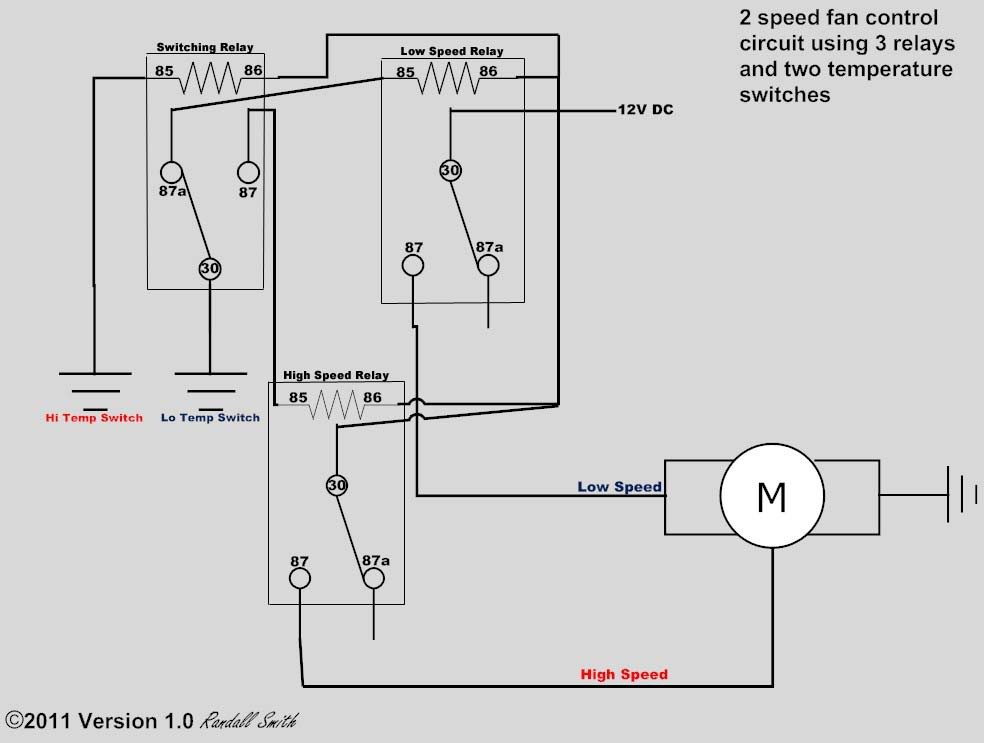
- Rectangle with coil: Represents a relay. Terminals are numbered: 30 - incoming power, 87 - outgoing power, 85 - relay coil ground, 86 - relay coil trigger.
- Zigzag line: Represents a resistor.
- Horizontal line connected to ground symbol: Represents ground connection.
- Small circle: Represents a wire splice or connection point.
- Labels: Text descriptions that identify the function of each component or wire.
Pay close attention to the wire colors and terminal numbers on the relays. These are crucial for identifying the correct connections.
Example:
Battery (+) ---- (Red Wire) ---- Fuse ---- (Red Wire) ---- Relay 1 (Terminal 30)
This simple snippet illustrates how the battery positive is connected via a red wire, protected by a fuse, and then connected to terminal 30 of a relay.
How It Works: The 2-Speed Fan in Action
The beauty of a 2-speed fan system lies in its simplicity. Here's how it generally works:
- Low Speed: When the engine temperature reaches a certain threshold, the temperature switch (or the ECU) activates the low-speed relay. This relay closes, sending power through the "low-speed" winding of the fan motor. The fan runs at a slower speed.
- High Speed: If the engine temperature continues to rise, the temperature switch (or the ECU) activates the high-speed relay (in some systems the low-speed relay remains active too). This relay closes, sending power through the "high-speed" winding of the fan motor (or both windings). The fan runs at a faster speed, providing more cooling.
Some systems use a series resistor to achieve the low speed, but this is less common than using separate windings within the motor.
Understanding the sequence of events allows you to isolate the problem. For example, if the low speed isn't working but the high speed is, you can focus on the low-speed relay, wiring, or the low-speed winding of the motor.
Real-World Use: Troubleshooting Tips
Here are some basic troubleshooting tips to help you diagnose common problems:
- Fan Not Working at All:
- Check the fuse. A blown fuse is the most common cause.
- Check the relays. Use a multimeter to test if the relays are receiving power and switching correctly. You can also swap relays with a known good one to see if that resolves the issue.
- Check the wiring. Look for loose connections, corroded terminals, or damaged wires.
- Test the fan motor directly. Apply 12V directly to the motor terminals to see if it spins. If it doesn't, the motor is likely faulty.
- Low Speed Not Working, High Speed Works:
- Check the low-speed relay and its associated wiring.
- Check the low-speed winding of the fan motor.
- High Speed Not Working, Low Speed Works:
- Check the high-speed relay and its associated wiring.
- Check the high-speed winding of the fan motor.
- Fan Runs Constantly:
- Check the temperature switch or ECU signal. It may be stuck in the "on" position.
- Check the relays. They may be stuck closed.
Always use a multimeter to test for voltage and continuity. This is the most effective way to pinpoint electrical problems.
Safety First!
Working with electrical systems can be dangerous. Keep these safety precautions in mind:
- Disconnect the Battery: Before working on any electrical components, disconnect the negative terminal of the battery to prevent short circuits and electrical shocks.
- Work in a Well-Ventilated Area: Some electrical components can release harmful fumes when heated.
- Use Insulated Tools: Protect yourself from electrical shock by using tools with insulated handles.
- Never Work on a Live Circuit: Unless absolutely necessary for testing, always disconnect the power before working on any wiring.
- Be Careful with Relays: Relays can get hot when they're switching. Avoid touching them immediately after they've been activated.
- Fuses: Always replace a blown fuse with a fuse of the same amperage rating. Using a higher amperage fuse can damage the circuit and create a fire hazard.
Remember that capacitors and large inductive loads can store charges even when the battery is disconnected. Discharge these components before working on them.
By understanding the wiring diagram and following these safety precautions, you can confidently tackle 2-speed fan motor repairs and upgrades. Good luck!
We have a downloadable PDF file of a typical 2-speed fan motor wiring diagram available for you. This diagram will be a valuable resource as you work on your car. Feel free to reach out if you have any questions about the diagram or the information provided in this article. Happy wrenching!