
Wiring Diagram For 3 Lights One Switch
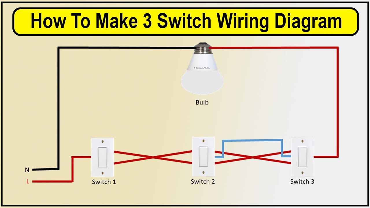
Alright, let's dive into wiring up three lights to a single switch. This is a common modification in automotive applications, whether you're adding auxiliary lights to your off-roader, upgrading interior lighting in your camper van, or just plain fixing some existing wiring. Understanding this basic circuit is a cornerstone for more complex electrical work, and it's a skill that will save you money and headaches down the road. We'll break down the wiring diagram, explain the key components, and provide some troubleshooting tips. Plus, we've got a downloadable diagram for your reference, which we'll mention at the end.
Purpose
Why bother learning this? The most straightforward reason is repair. If your existing lights controlled by a single switch aren't working, tracing the wiring and understanding the circuit is essential for diagnosis and repair. Another reason is modification. Say you want to add a light bar and two flood lights to your truck; this is the exact setup you need. Finally, understanding this simple circuit is a stepping stone to mastering more complex automotive electrical systems. It's a foundational skill for any serious DIY mechanic or automotive enthusiast. This knowledge helps you diagnose issues faster and perform modifications safely and efficiently.
Key Specs and Main Parts
Before we get to the diagram itself, let's define the key components and the specs you need to keep in mind. We're dealing with a low-voltage DC (Direct Current) system, typically 12V in most automotive applications.
- Power Source: This is your car's battery (12V). It provides the electrical energy to power the lights. Ensure your lights are designed to operate on 12V DC.
- Fuse: This is a critical safety device. It's a sacrificial component designed to break the circuit if the current draw exceeds a safe level. This prevents damage to your wiring and components, and more importantly, prevents fires. The fuse rating (e.g., 10A, 15A) should be appropriate for the total power consumption of the three lights. Too low, and it will blow frequently; too high, and it won't protect the circuit properly. Calculate the total current draw by adding the current draw of each light (Power (Watts) / Voltage (Volts) = Current (Amps)).
- Switch: This is the control point. It's a simple on/off switch that connects or disconnects the circuit, allowing current to flow to the lights when "on" and stopping the flow when "off." Make sure your switch is rated for the voltage and current it will be handling. Look for a switch with a DC voltage rating of 12V or higher and a current rating equal to or greater than the total current draw of your lights.
- Wiring: The conductive pathways that carry the electrical current. Wire gauge (thickness) is critical. Thicker wires can handle more current without overheating. Use a wire gauge that's appropriate for the current draw. An 18-gauge wire might be sufficient for low-wattage lights, but for higher-wattage lights, you'll need 16-gauge or even 14-gauge wire. Overloading wires can lead to overheating, melting insulation, and even fires. Always err on the side of caution and use a thicker wire than you think you need.
- Lights (Loads): These are the devices that consume the electrical energy and produce light. They can be incandescent bulbs, halogen bulbs, LEDs, or other types of lighting.
- Ground: The return path for the electrical current, connected to the vehicle's chassis or a dedicated grounding point. A good ground connection is essential for the circuit to function correctly. A poor ground can cause flickering lights, dim lights, or even prevent the lights from working altogether.
- Connectors/Terminals: Used to make secure and reliable electrical connections. Crimp connectors, butt connectors, and ring terminals are common.
Symbols
Understanding the symbols in the wiring diagram is crucial for interpreting it correctly:
- Solid Lines: Represent wires. The thickness of the line doesn't necessarily indicate wire gauge, but it's sometimes used to differentiate power wires from signal wires in more complex diagrams.
- Dashed Lines: Often represent connections to the chassis ground.
- Colors: Wires are often color-coded for identification. Common colors are:
- Red: Typically used for positive (+) power wires.
- Black: Typically used for ground (-) wires.
- Other Colors (e.g., Blue, Yellow, Green): Used for signal wires or other specific functions.
- Battery Symbol: A series of short and long parallel lines represents the battery. The longer line typically indicates the positive (+) terminal.
- Fuse Symbol: A squiggly line or a rectangle with a line through it represents the fuse.
- Switch Symbol: A line that can be connected or disconnected to another line represents the switch.
- Light Bulb Symbol: A circle with an "X" inside it represents a light bulb. More modern diagrams might use a symbol resembling an LED.
- Ground Symbol: A series of decreasing lines, often resembling an inverted triangle, represents the ground connection.
How It Works
The circuit works on a simple principle: completing a path for electrical current to flow. Current flows from the positive (+) terminal of the battery, through the fuse (for protection), to the switch. When the switch is closed (turned "on"), it allows the current to flow through the wiring to each of the three lights. The lights consume the electrical energy, producing light. From the lights, the current flows through the ground wires back to the negative (-) terminal of the battery, completing the circuit.
The key to wiring the three lights to a single switch is to wire them in parallel. This means that each light has its own path to ground, independent of the other lights. If one light fails, the other two will continue to function. In a series connection, if one light fails, the entire circuit breaks, and all the lights go out.
In a parallel configuration, the voltage across each light is the same (12V), but the current is divided between the lights. This is why it's crucial to calculate the total current draw and choose a fuse and wire gauge that can handle it. The positive wires for each light need to be spliced together after the switch. Ideally, you use proper wiring connectors to ensure reliable connections. Similarly, the ground wires from each light need to be joined to a common ground point on the vehicle's chassis.
Real-World Use – Basic Troubleshooting Tips
Here are some common problems you might encounter and how to troubleshoot them:
- Lights Don't Turn On:
- Check the Fuse: This is the first and easiest step. If the fuse is blown, replace it with a fuse of the same rating. If the fuse blows again immediately, there's a short circuit in the wiring.
- Check the Switch: Use a multimeter to test if the switch is working correctly. With the switch in the "on" position, you should see continuity between the two terminals.
- Check the Ground Connections: Ensure that the ground connections are clean and secure. A loose or corroded ground connection can prevent the circuit from working.
- Check the Wiring: Look for any damaged or frayed wires. Use a multimeter to check for continuity between different points in the circuit.
- Test the Lights Individually: Disconnect each light and test it directly with a 12V power source to make sure the light itself is functioning.
- Lights are Dim:
- Check the Ground Connections: This is the most common cause of dim lights.
- Check the Voltage: Use a multimeter to measure the voltage at the lights. If the voltage is significantly lower than 12V, there may be excessive voltage drop in the wiring. This could be due to undersized wires, poor connections, or a corroded ground.
- Fuse Keeps Blowing:
- Check for Short Circuits: A short circuit occurs when a positive wire comes into contact with a ground wire. This can be caused by damaged insulation or loose connections. Carefully inspect the wiring for any signs of damage.
- Overload: Make sure you haven't exceeded the fuse's current rating by adding too many lights or lights that draw too much power.
Safety
Working with automotive electrical systems can be dangerous. Here are some critical safety precautions:
- Disconnect the Battery: Before working on any electrical circuit, disconnect the negative (-) terminal of the battery. This prevents accidental short circuits and shocks.
- Use Proper Tools: Use insulated tools designed for electrical work.
- Wear Safety Glasses: Protect your eyes from sparks and debris.
- Never Work Alone: It's always a good idea to have someone nearby in case of an emergency.
- Be Aware of the High-Current Components: The battery and the main wiring harness can carry very high currents. Avoid touching exposed wires or terminals. A short circuit can cause a fire or serious injury.
- Double-Check Your Work: Before reconnecting the battery, carefully inspect your wiring to make sure everything is connected correctly and that there are no loose connections or exposed wires.
Remember, electrical work can be challenging, and if you're not comfortable with it, it's always best to consult a qualified automotive electrician.
For your convenience, we have created a downloadable wiring diagram for the three lights, one switch configuration discussed here. It visually represents the circuit layout, component placement, and wire connections, making it easier to understand and implement the wiring project.