
Wiring Diagram For 6 Wire Trailer Plug
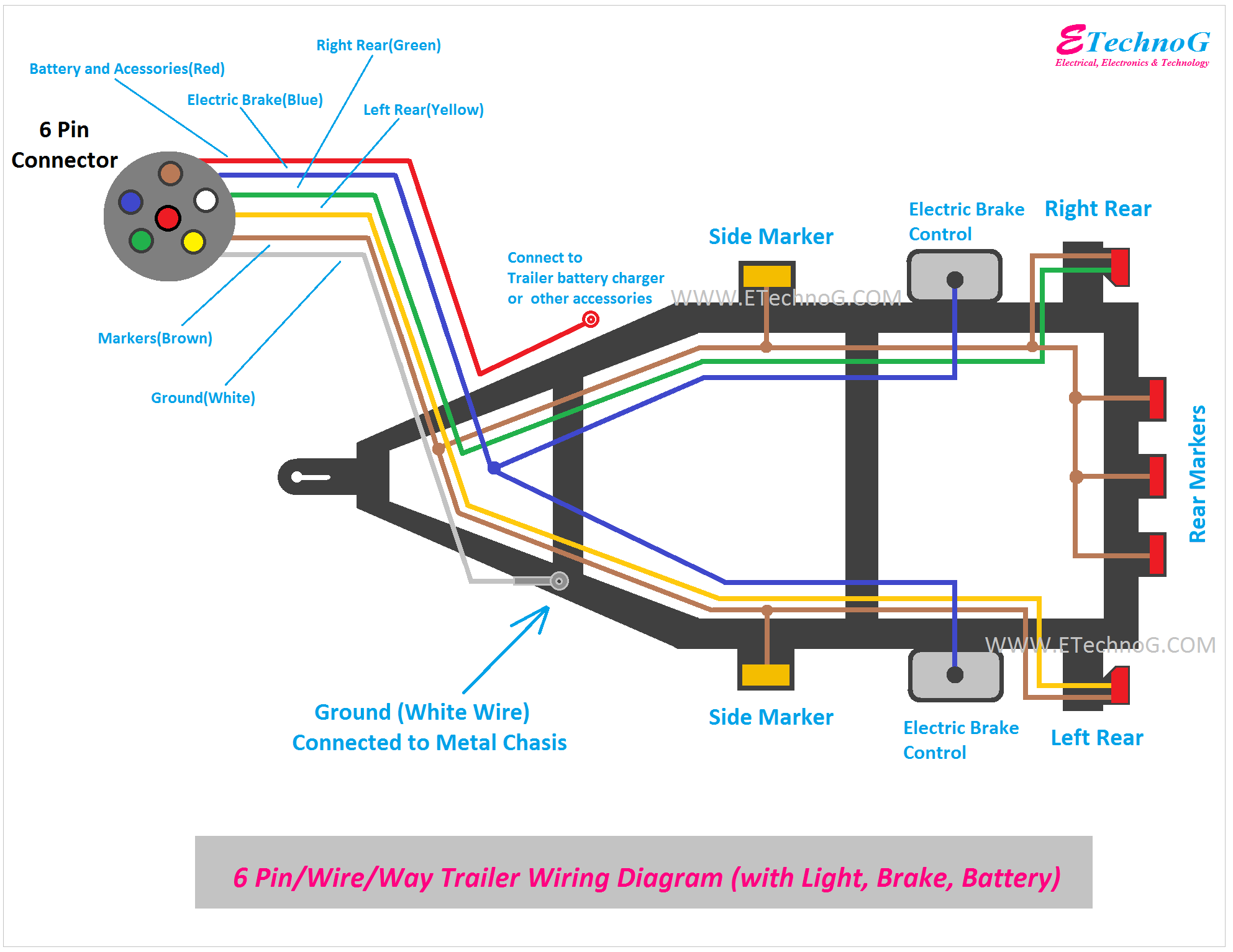
So, you're tackling a 6-wire trailer plug wiring project? Excellent! This guide will arm you with the knowledge to confidently wire (or rewire) your trailer connection. Whether you’re troubleshooting faulty lights, upgrading your setup, or simply expanding your automotive know-how, understanding the 6-wire trailer plug is a valuable skill. We'll break down the wiring diagram step-by-step, covering everything from its purpose to practical troubleshooting.
Purpose of a 6-Wire Trailer Plug Wiring Diagram
The 6-wire trailer plug wiring diagram serves as your roadmap for connecting the electrical systems of your tow vehicle and trailer. It visually represents the exact function of each wire, ensuring that your trailer lights, brakes (if equipped), and auxiliary power sources function correctly and safely. Using a diagram avoids guesswork, preventing short circuits, blown fuses, and potential damage to your vehicle's electrical system, or even worse, an accident on the road due to non-functional trailer lights.
The diagram is invaluable for:
- Repairs: Identifying and fixing broken or corroded wires.
- New Installations: Wiring a trailer from scratch or installing a new trailer connector on your tow vehicle.
- Troubleshooting: Diagnosing lighting or braking issues by verifying correct wiring.
- Modifications: Adding or changing trailer functions, such as auxiliary power or backup lights.
- Education: Understanding the electrical principles behind trailer wiring.
Key Specs and Main Parts
Before diving into the diagram itself, let’s define the critical components involved. The 6-wire system represents a common configuration offering more functionality than a basic 4-wire system. The core difference is the inclusion of a dedicated wire for electric trailer brakes, backup lights, or auxiliary power. The main parts you will deal with are the plug and receptacle themselves, and the wiring harness attached to each.
Plug and Receptacle
The trailer plug (the part attached to the trailer) and the vehicle receptacle (the part mounted on the tow vehicle) are designed to mate securely. They are typically made of durable plastic or metal and have six pins or sockets corresponding to the six wires.
Wiring Harness
The wiring harness is the bundle of wires connecting the trailer plug to the trailer's electrical components and the vehicle receptacle to the vehicle's electrical system. Wire gauge (thickness) is important. Typically, heavier gauge wires are used for functions requiring higher current, such as brake control.
Wire Gauge (AWG)
The American Wire Gauge (AWG) system is a standardized method of denoting wire diameter. Lower AWG numbers indicate thicker wires with greater current-carrying capacity. For trailer wiring, 12 or 14 AWG is common for most functions. Brake circuits might even use 10 AWG on larger trailers.
Symbols, Colors, and Icons in a Wiring Diagram
Understanding the language of a wiring diagram is crucial for its effective use. Here's a breakdown of common symbols and conventions:
Lines
- Solid Lines: Represent individual wires connecting electrical components.
- Dashed Lines: May indicate optional or less common connections.
Colors
While wire color codes can vary slightly depending on the manufacturer, certain color standards are widely adopted. Here's a typical color code for a 6-wire trailer plug:
- White: Ground (GND) – Connects to the vehicle's chassis for a return path.
- Brown: Tail Lights/Running Lights – Powers the rear taillights, side marker lights, and license plate light.
- Yellow: Left Turn/Stop Light – Powers the left turn signal and brake light.
- Green: Right Turn/Stop Light – Powers the right turn signal and brake light.
- Blue: Electric Brake Controller Output – Connects to the brake controller in the tow vehicle. This must be a dedicated circuit.
- Red or Black: Auxiliary Power – Provides 12V DC power for trailer accessories (interior lights, battery charging, etc.). Often protected by a fuse.
Important Note: Always double-check the specific color code for your trailer and vehicle wiring harnesses, as manufacturers may deviate from the standard. Use a multimeter to verify the function of each wire if you are unsure.
Icons
Standard electrical symbols represent components like:
- Light Bulbs: Indicate lighting circuits.
- Fuses: Show overcurrent protection.
- Ground Symbols: Represent the connection to the vehicle's chassis.
- Battery Symbols: Indicate a power source.
- Switches: Control the flow of electricity in a circuit.
How It Works: The 6-Wire System in Action
The 6-wire trailer plug allows for the safe and reliable operation of essential trailer functions. Let's trace the path of each wire and its corresponding function:
- White (Ground): Provides a return path for the electrical current to the vehicle's battery. A good ground connection is critical for all trailer functions to work correctly.
- Brown (Tail Lights): When the vehicle's headlights or parking lights are activated, power flows through the brown wire to illuminate the trailer's tail lights, side marker lights, and license plate light.
- Yellow (Left Turn/Stop): When the vehicle's left turn signal is activated, or the brakes are applied, power flows through the yellow wire to illuminate the trailer's left turn signal and brake light.
- Green (Right Turn/Stop): Similar to the yellow wire, power flows through the green wire when the vehicle's right turn signal is activated, or the brakes are applied, illuminating the trailer's right turn signal and brake light.
- Blue (Electric Brake Controller): When the driver applies the vehicle's brakes, the electric brake controller sends a signal through the blue wire to activate the trailer's electric brakes. The amount of braking force applied to the trailer is typically proportional to the braking force applied to the tow vehicle. This requires a separate, properly installed brake controller inside the tow vehicle.
- Red or Black (Auxiliary Power): This wire provides a constant 12V DC power source to the trailer, allowing for the operation of interior lights, battery charging, or other auxiliary functions. This circuit should always be fused to protect against short circuits.
Real-World Use: Basic Troubleshooting
Here are a few basic troubleshooting tips you can use to diagnose common problems with your 6-wire trailer connection:
- No Lights: Check the ground connection first. A poor ground is the most common cause of lighting problems. Clean and tighten the ground connection on both the trailer and the vehicle. Also, check fuses in both the tow vehicle and the trailer.
- One Light Not Working: Check the bulb first. If the bulb is good, use a multimeter to check for voltage at the light socket when the corresponding signal (turn signal, brake light) is activated. If there's no voltage, trace the wire back to the connector, looking for breaks or corrosion.
- Brakes Not Working: Verify that the brake controller in the tow vehicle is properly installed and functioning. Check the blue wire connection at both the trailer plug and the brake controller. Also, inspect the trailer's brake magnets for damage or wear.
- Erratic Lighting: This is often caused by a loose connection or corrosion. Carefully inspect all connections and clean them with electrical contact cleaner.
Safety Precautions
Working with electrical systems involves inherent risks. Here are some crucial safety precautions to follow:
- Disconnect the Battery: Always disconnect the negative battery cable from both the tow vehicle and the trailer before working on the wiring. This prevents accidental short circuits and electrical shocks.
- Use the Right Tools: Use properly insulated tools designed for electrical work.
- Wear Safety Glasses: Protect your eyes from flying debris or sparks.
- Work in a Well-Ventilated Area: Some electrical cleaners and solvents can produce harmful fumes.
- Fuse Protection: Always use fuses of the correct amperage rating to protect the electrical circuits. Over-fusing can lead to overheating and fire.
- Proper Wiring Techniques: Use proper crimping and soldering techniques to ensure secure and reliable connections. Avoid using wire nuts, which are not suitable for automotive applications.
- Inspect Wiring Regularly: Regularly inspect the trailer wiring for signs of damage, wear, or corrosion. Replace any damaged wires or connectors immediately.
- Brake Controller Wiring: The electric brake controller wire, the blue wire, draws significant current. Never splice into another circuit for this connection. Always use a dedicated wire run directly from the vehicle's battery, through a circuit breaker, to the brake controller.
Remember, working with electricity can be dangerous. If you are not comfortable performing electrical work, consult a qualified mechanic or electrician.
With this knowledge, you're well-equipped to tackle your 6-wire trailer wiring project. By understanding the purpose, components, and safety considerations outlined in this guide, you can ensure a safe and reliable connection between your tow vehicle and trailer.
We have a detailed wiring diagram file available for download. This diagram provides a visual representation of the wiring connections, making it easier to follow and understand the wiring process. This diagram includes color-coding, wire functions, and component locations for 6-wire trailer plugs. This will certainly help in your wiring or repair project.