
Wiring Diagram For A One Wire Alternator
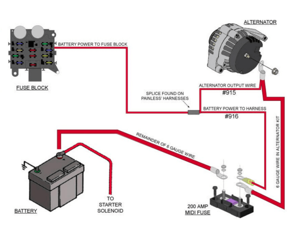
So, you're thinking about tackling a one-wire alternator conversion? Excellent choice! These alternators offer a cleaner, simpler wiring setup compared to traditional three-wire systems, making them a popular upgrade for older vehicles, street rods, or any project where you're looking to declutter the engine bay. This article dives into the wiring diagram for a one-wire alternator, explaining everything you need to know to install, troubleshoot, and understand how it all works. We've also got a downloadable diagram you can use as a reference.
Purpose of Understanding the Wiring Diagram
Why bother understanding the wiring diagram? Several reasons:
- Installation Accuracy: A clear understanding prevents wiring errors that could damage the alternator, the vehicle's electrical system, or both.
- Troubleshooting: When issues arise (charging problems, flickering lights), the diagram is your roadmap to diagnosing the problem quickly and efficiently.
- Customization: Want to add a voltmeter or other monitoring device? The diagram will guide you in making safe and effective connections.
- General Knowledge: Understanding the basics of how an alternator works and how it's wired provides a solid foundation for tackling other automotive electrical projects.
Key Specs and Main Parts
Before we dive into the diagram itself, let's clarify the key specs and main parts involved:
- One-Wire Alternator: This is the star of the show. Unlike a three-wire alternator, it only requires one heavy-gauge wire connected directly to the battery positive (+) terminal. The internal voltage regulator handles the rest.
- Battery: The heart of your electrical system. The alternator's primary job is to keep the battery charged.
- Battery Positive (+) Cable: A thick cable (typically 4 gauge or larger) connects the alternator output terminal to the battery positive (+) terminal or a distribution block connected to the battery positive terminal. This carries the charging current.
- Ground Connection: The alternator case MUST be properly grounded to the engine block, which, in turn, must be grounded to the vehicle's chassis and battery negative (-). A poor ground is a common cause of alternator problems.
- Fuse (Optional but Recommended): Installing a high-amperage fuse in the battery positive cable near the battery is a smart safety precaution. It protects the wiring and the alternator from short circuits. Choose a fuse rated slightly higher than the alternator's maximum output (e.g., a 150-amp fuse for a 100-amp alternator).
- Voltmeter (Optional): A gauge to monitor the charging voltage. It should read between 13.5 and 14.5 volts when the engine is running.
Symbols in the Wiring Diagram
Understanding the symbols used in a wiring diagram is crucial for interpreting it correctly. Here's a breakdown of common symbols:
- Solid Lines: Represent wires. The thicker the line, the larger the wire gauge.
- Dashed Lines: Often indicate optional connections or grounds.
- Colors: Wire colors are typically indicated using abbreviations (e.g., RED for red, BLK for black, BLU for blue). These colors help you identify the correct wires in the vehicle.
- Battery Symbol: A series of short and long parallel lines indicating the battery's positive and negative terminals.
- Ground Symbol: Usually a series of horizontal lines descending to a point, representing a connection to the vehicle's chassis.
- Alternator Symbol: Varies slightly depending on the diagram, but often depicts a circle with the letter "A" inside or a stylized representation of an alternator.
- Fuse Symbol: A squiggly line inside a rectangle or a simple rectangle with a line through it.
- Circle with a + sign: Typically represents the alternator's output terminal.
How a One-Wire Alternator Works
Here's a simplified explanation of how a one-wire alternator functions:
When the engine starts, the alternator begins to spin. The rotor inside the alternator is magnetized. As the rotor spins within the stator (a set of stationary coils), it generates alternating current (AC). This AC is then converted to direct current (DC) by the rectifier (usually a set of diodes). The internal voltage regulator monitors the output voltage. When the voltage reaches a preset level (typically around 14 volts), the regulator reduces the current flowing to the rotor, preventing overcharging. Because it's a "one-wire" alternator, it self-excites once it reaches a certain RPM and doesn't need an external signal to start charging.
Unlike a three-wire alternator which requires an external voltage signal to "excite" the alternator to begin charging, the one-wire alternator builds voltage as it spins. Once the alternator reaches a certain RPM, the internal regulator allows the alternator to begin charging. Once the voltage in the charging system increases to 13.5 volts or above, the alternator will continue charging, even at lower RPMs.
Real-World Use – Basic Troubleshooting Tips
Here are some common problems and how to troubleshoot them using the wiring diagram as a guide:
- No Charging:
- Check the main battery positive cable. Is it securely connected to both the alternator and the battery (or distribution block)?
- Verify the ground connection. Clean and tighten the connections between the alternator case, the engine block, the chassis, and the battery negative (-). A poor ground is a VERY common culprit.
- Check the fuse (if installed). Is it blown? If so, replace it with a fuse of the same amperage rating. If the fuse blows repeatedly, there's likely a short circuit in the wiring.
- Check the belt. Is the belt slipping or broken? If so, the alternator is not spinning at the correct speed.
- Overcharging:
- Suspect a faulty internal voltage regulator. A multimeter can check the alternator's output voltage while running. If it consistently exceeds 14.5 volts, the regulator is likely the problem and the alternator should be replaced or rebuilt.
- Flickering Lights:
- Could indicate a loose connection or a grounding issue. Carefully inspect all connections in the charging circuit, paying close attention to the ground connections.
- Low Voltage Reading:
- Check for voltage drop along the charging cable. High resistance due to corrosion or a damaged cable can reduce the charging voltage. Use a multimeter to measure voltage at both ends of the cable while the alternator is charging. A significant voltage difference indicates a problem with the cable.
Safety Precautions
Working with automotive electrical systems involves inherent risks. Keep these safety precautions in mind:
- Disconnect the Battery: ALWAYS disconnect the battery negative (-) cable before working on any electrical components. This prevents accidental shorts and potential electric shock.
- Wear Safety Glasses: Protect your eyes from debris and accidental sparks.
- Use Insulated Tools: Use tools with insulated handles to minimize the risk of electric shock.
- Be Careful with High-Amperage Components: The battery positive cable and the alternator output terminal carry high amperage. Avoid accidentally shorting these to ground.
Get Your Diagram
Now that you have a grasp of the concepts, having a visual aid is invaluable. We've prepared a downloadable wiring diagram specifically for one-wire alternators. This diagram provides a clear and concise illustration of the connections discussed in this article. Download the file now to help you visualize your project and ensure a successful installation.
With a little planning and by following these guidelines, you can confidently tackle the wiring of a one-wire alternator. Good luck with your project!