
Wiring Diagram For A Starter Solenoid
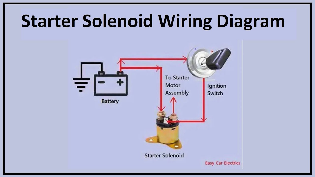
So, you're tackling a starter solenoid issue, or maybe you're just trying to understand your car's starting system better? Either way, understanding the wiring diagram for your starter solenoid is crucial. It's the roadmap to diagnosing problems, making repairs, and even doing some cool performance upgrades. This article will break down the diagram step-by-step, assuming you have some basic mechanical knowledge but aren't necessarily an electrical whiz. We'll cover everything from the components and symbols to troubleshooting and safety.
Why Bother with a Wiring Diagram?
Let's be honest, cars are getting more complex, not less. Sticking your head under the hood and randomly yanking wires is a recipe for disaster (and an expensive tow). A wiring diagram gives you a visual representation of the electrical circuit, allowing you to:
- Diagnose Starting Problems: Is the starter motor not turning? Is it clicking? The diagram helps you pinpoint the fault – a bad solenoid, a wiring issue, or a faulty ignition switch.
- Perform Repairs Safely: Knowing where each wire goes prevents accidental shorts or reversed polarities, which can damage components and potentially cause injury.
- Understand the System: Even if you're not fixing anything right now, understanding the starting circuit gives you a deeper understanding of how your car works.
- Plan Modifications: Upgrading your starter motor, adding a remote start system, or even installing a kill switch requires understanding the wiring.
Key Specs and Main Parts of a Starter Solenoid Circuit
Before diving into the diagram itself, let's identify the key components and their roles:
- Battery: The heart of the electrical system, providing the power needed to crank the engine.
- Ignition Switch: This acts as the control switch. When you turn the key, it sends a signal to the solenoid.
- Starter Solenoid: This is an electromagnetic switch. When it receives power from the ignition switch, it closes a high-current circuit between the battery and the starter motor. It also mechanically engages the starter pinion gear with the engine's flywheel.
- Starter Motor: This powerful electric motor spins the engine's flywheel, initiating the combustion process.
- Ground (Chassis): The return path for the electrical current. Usually, the negative terminal of the battery is connected to the car's chassis, which acts as a common ground point.
- Fuses/Fusible Links: Safety devices that protect the circuit from overcurrents. These are designed to blow, breaking the circuit, if too much current flows through them.
- Relays (Optional): In some vehicles, a relay is used between the ignition switch and the solenoid to reduce the load on the ignition switch.
Key Specs you might encounter:
- Voltage: Typically 12V DC in most cars.
- Current Rating: Starter motors draw a significant amount of current (hundreds of amps) during starting. The solenoid and associated wiring must be rated to handle this current.
- Wire Gauge: The thickness of the wires is crucial. Thicker wires can carry more current without overheating. Pay attention to the wire gauge specified in the diagram.
Decoding the Wiring Diagram Symbols
Wiring diagrams use a standardized set of symbols to represent electrical components. Here are some of the most common symbols you'll see in a starter solenoid wiring diagram:
- Straight Lines: These represent wires. The thickness of the line may sometimes indicate the wire gauge (thicker = larger gauge).
- Dotted Lines: These often indicate shielded wires or wires that are optional or part of a sub-circuit.
- Battery Symbol: Two unequal parallel lines. The longer line represents the positive (+) terminal, and the shorter line represents the negative (-) terminal.
- Ground Symbol: Usually represented by a series of horizontal lines tapering to a point, resembling an upside-down Christmas tree, or a triangle connected to a horizontal line.
- Resistor Symbol: A zigzag line.
- Switch Symbol: A line that can be open or closed to connect or disconnect a circuit. The ignition switch is typically shown as a multi-position switch.
- Solenoid Symbol: Often a coil of wire with a plunger or actuator.
- Fuse Symbol: A zigzag line inside a rectangle or a straight line with a bump in the middle.
- Motor Symbol: A circle with an "M" inside.
Colors: Wire colors are crucial for identifying the correct wires. Common colors include red (power), black (ground), yellow, blue, green, and white. Color codes are usually abbreviated (e.g., RED, BLK, YEL). A legend on the diagram will typically list all the color codes used.
How the Starter Solenoid Circuit Works
Here's a simplified breakdown of how the starter solenoid circuit operates:
- Turning the Key: When you turn the ignition key to the "start" position, you close a circuit.
- Signal to the Solenoid: This sends a low-current signal (12V) from the ignition switch to the solenoid's control winding (often called the "S" terminal).
- Solenoid Activation: The current flowing through the solenoid's winding creates a magnetic field. This magnetic field pulls a plunger inside the solenoid.
- Closing the High-Current Circuit: The plunger does two things:
- It closes a heavy-duty switch inside the solenoid, connecting the battery directly to the starter motor. This is the high-current circuit.
- It mechanically engages the starter pinion gear with the engine's flywheel (on most starters).
- Starter Motor Activation: The high current from the battery flows through the starter motor, causing it to spin and crank the engine.
- Releasing the Key: When you release the key, the ignition switch opens, cutting off the signal to the solenoid. The magnetic field collapses, the plunger retracts, the high-current circuit opens, and the starter motor stops.
Real-World Use: Basic Troubleshooting
Let's say your car won't start. Here are some troubleshooting tips using the wiring diagram:
- No Click, No Crank:
- Check the battery voltage. Is it below 12V?
- Check the ignition switch. Is it functioning properly? Use a multimeter to check for voltage at the "S" terminal of the solenoid when the key is in the "start" position.
- Check the solenoid itself. If you have voltage at the "S" terminal but the starter motor doesn't engage, the solenoid might be faulty. You can try bypassing the solenoid (carefully!) by jumping the two large terminals with a screwdriver. Warning: This will create a large spark and bypass all safety circuits. Only do this briefly for testing purposes.
- Check the wiring for breaks or corrosion. Use a multimeter to check for continuity in the wires.
- Clicking Sound, No Crank:
- This often indicates a weak battery or poor connection. Check the battery terminals and cables for corrosion. Clean them thoroughly.
- It could also be a faulty solenoid. The solenoid might be engaging but not making a good connection in the high-current circuit.
- Starter Motor Spins but Doesn't Engage:
- This indicates a problem with the mechanical engagement of the starter pinion gear. The solenoid might be working electrically but not mechanically engaging the gear. This usually means the starter motor needs to be replaced or rebuilt.
Safety First!
Working with electrical systems, especially high-current circuits like the starter circuit, can be dangerous. Here are some crucial safety precautions:
- Disconnect the Battery: Always disconnect the negative (-) battery terminal before working on the electrical system. This prevents accidental shorts and potential shocks.
- Use the Right Tools: Use insulated tools to avoid electric shock.
- Be Aware of High Current: The starter motor draws a huge amount of current. Never touch the terminals or wires while the engine is cranking.
- Avoid Flammable Materials: Batteries can produce flammable gases. Avoid sparks or open flames near the battery.
- Proper Grounding: Ensure all components are properly grounded. Poor grounding can cause electrical problems and even fires.
- Fuses are your friends. Never bypass fuses. If a fuse blows repeatedly, it indicates a problem in the circuit that needs to be addressed. Bypassing a fuse can lead to a fire.
The starter solenoid wiring diagram is an essential tool for diagnosing and repairing starting problems. By understanding the components, symbols, and how the circuit works, you can tackle these issues safely and effectively. Remember to always prioritize safety and use the right tools for the job.
We have a generic starter solenoid wiring diagram available as a downloadable file to help you visualize the concepts discussed. It's a PDF and will serve as a general reference. Keep in mind that your specific vehicle's wiring might differ slightly, so always consult the factory service manual for the most accurate diagram. Contact us and we'll send you the file.