Wiring Diagram For A Switched Outlet
Alright, let's dive into wiring a switched outlet. Whether you're tackling a faulty circuit, adding convenience to your garage, or simply expanding your electrical know-how, understanding how a switched outlet works is crucial. This guide provides a detailed breakdown of the wiring diagram, empowering you to confidently tackle electrical projects.
Purpose of Understanding the Wiring Diagram
Why bother understanding this? Simple: safety and functionality. A wiring diagram isn't just a drawing; it's your roadmap to a properly functioning and, most importantly, safe electrical system. Using it lets you:
- Troubleshoot Electrical Issues: Pinpoint problems quickly and efficiently. Is the light not turning on? Is the outlet dead? The diagram helps you trace the circuit.
- Perform Repairs Safely: When fixing faulty wiring, the diagram ensures you're connecting wires correctly.
- Add New Outlets or Switches: Extend your electrical system with confidence, knowing you're following established procedures.
- Deepen Your Electrical Understanding: Electrical skills can save you money. Understanding this diagram unlocks more electrical projects.
Without a solid understanding of the wiring diagram, you're essentially working blind, which can lead to damage, fire hazards, or even electrical shock.
Key Specs and Main Parts of a Switched Outlet Circuit
Before we look at the diagram, let's identify the main components you'll find in a typical switched outlet circuit:
- Power Source (Circuit Breaker): This is where the electricity originates. Always disconnect the circuit breaker before working on any electrical circuit!
- Wiring:
- Hot Wire (Black): Carries the electricity from the power source.
- Neutral Wire (White): Returns the electricity back to the power source.
- Ground Wire (Green or Bare): Provides a safe path for electricity in case of a fault.
- Switch: Controls the flow of electricity to the outlet.
- Outlet (Receptacle): Provides a point to plug in electrical devices. A standard outlet has two slots: a larger slot for the neutral wire and a smaller slot for the hot wire, and a D-shaped hole for the ground wire.
- Wire Connectors (Wire Nuts): Insulated caps used to connect two or more wires together.
- Junction Box: A protective enclosure for electrical connections.
Understanding Wiring Diagram Symbols
A wiring diagram uses a standardized set of symbols to represent electrical components. Here’s a breakdown of the common symbols you'll encounter:
- Lines: Indicate wires connecting different components. Solid lines typically represent hot or neutral wires, while dashed or dotted lines might represent ground wires or alternative connections.
- Colors: Wire colors are critical for identification.
- Black (Hot): The primary conductor carrying electricity.
- White (Neutral): The return path for electricity.
- Green or Bare (Ground): Safety conductor, providing a path for fault current.
- Switch Symbols: Represent the switch. Common symbols include a circle with a line extending to another circle, indicating the switch contacts.
- Single-Pole, Single-Throw (SPST) Switch: The most common type, controlling one circuit from one location.
- Outlet Symbol: Typically a circle with two lines extending from it, representing the slots for plugging in devices. Sometimes, it will have a third line or dot for the ground connection.
- Junction Box Symbol: Usually a rectangle or square, representing the enclosure where wires are connected.
- Circuit Breaker Symbol: Often represented as a small rectangle with a line through it, or a stylized switch symbol.
The wiring diagram itself will show how these symbols are connected, indicating the path of electricity through the circuit.
How a Switched Outlet Works
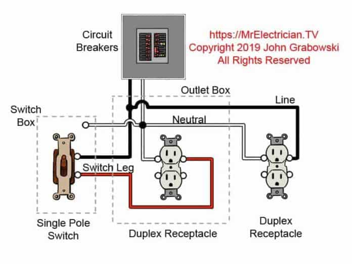
The basic principle is quite simple: the switch interrupts the flow of the hot wire to the outlet. Here's the typical wiring sequence:
- The hot wire from the circuit breaker enters the first junction box.
- The hot wire is connected to one terminal of the switch.
- Another hot wire runs from the other terminal of the switch to the hot terminal of the outlet. This wire is often called the "switched hot" wire.
- The neutral wire from the circuit breaker runs directly to the neutral terminal of the outlet.
- The ground wire from the circuit breaker runs to the ground terminal of the outlet AND is connected to the metal box (if applicable) and switch's ground if equipped.
When the switch is in the "on" position, it closes the circuit, allowing electricity to flow from the hot wire, through the switch, to the outlet. This allows you to plug in a lamp, appliance, or other device and have it function. When the switch is in the "off" position, it opens the circuit, interrupting the flow of electricity to the outlet, effectively turning it off.
Real-World Use: Basic Troubleshooting Tips
Okay, so you've wired a switched outlet, and it's not working. Don't panic! Here are a few basic troubleshooting steps:
- Check the Circuit Breaker: This is the first and easiest step. Make sure the breaker hasn't tripped. Reset it if necessary.
- Test for Voltage: Use a non-contact voltage tester to check if the hot wire is actually carrying electricity. If there's no voltage at the outlet or switch, the problem might be further upstream (closer to the breaker panel).
- Inspect Wire Connections: Make sure all wire connections are secure. Loose connections are a common cause of electrical problems. Gently tug on each wire to ensure it's firmly held by the wire connector.
- Check the Switch: Sometimes, the switch itself can be faulty. You can use a multimeter to test the switch for continuity. When the switch is "on," there should be continuity between the terminals. When it's "off," there should be no continuity.
- Examine the Outlet: Check the outlet for any signs of damage, such as cracks or burns. If the outlet is damaged, replace it.
- Confirm Wiring Accuracy: Double-check that the wiring matches the wiring diagram. Incorrect wiring can cause all sorts of problems.
Important: If you're uncomfortable working with electricity, it's always best to call a qualified electrician. Don't take risks with your safety.
Safety: Highlight Risky Components
Electricity is dangerous, and safety is paramount. Here are some critical safety points:
- Always Disconnect Power: Turn off the circuit breaker before working on any electrical circuit. Double-check with a non-contact voltage tester to ensure the power is off.
- Use Insulated Tools: Use tools with insulated handles to protect yourself from electrical shock.
- Never Work in Wet Conditions: Water conducts electricity, so never work on electrical circuits in wet or damp environments.
- Wear Safety Glasses: Protect your eyes from sparks or debris.
- Respect Voltage: Remember that even low-voltage circuits can be dangerous. Treat all electrical circuits with respect.
- Grounding is Crucial: Ensure all ground wires are properly connected. Grounding provides a safe path for electricity in case of a fault.
- Don't Overload Circuits: Know the amperage rating of your circuit breaker and avoid plugging in too many devices. Overloading a circuit can cause the breaker to trip or, in more serious cases, start a fire.
- Don't Skimp on Materials: Use only high-quality electrical components that are rated for the voltage and amperage of the circuit.
Remember, when dealing with electricity, it’s better to be safe than sorry. If in doubt, consult a qualified electrician.
We have a complete switched outlet wiring diagram file available for download. This diagram includes detailed illustrations and specific wiring instructions to guide you through your project.