Wiring Diagram For Air Compressor Pressure Switch
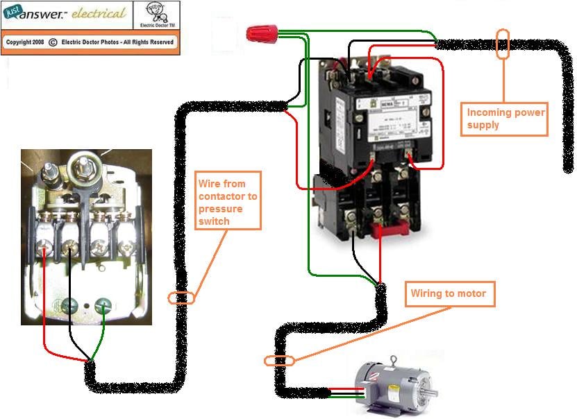
Understanding the wiring diagram for your air compressor's pressure switch is crucial for a variety of reasons. Whether you're diagnosing a malfunctioning compressor, performing routine maintenance, upgrading components, or even building your own custom setup, a solid grasp of the wiring is essential. This article provides a detailed explanation of a typical air compressor pressure switch wiring diagram, geared towards experienced DIYers like yourself.
Why This Diagram Matters
Think of the pressure switch as the brain of your air compressor. It monitors the tank pressure and tells the motor when to start and stop, maintaining a specific pressure range. A faulty pressure switch, or incorrect wiring to it, can lead to several problems:
- Compressor not turning on: If the switch isn't signaling the motor, you get no air.
- Compressor not turning off: Over-pressurization is dangerous and can damage your tank.
- Erratic cycling: Frequent starts and stops shorten the motor's lifespan.
- Blown fuses or tripped breakers: Wiring issues can cause electrical overloads.
Having a clear understanding of the wiring diagram enables you to effectively troubleshoot these issues, ensuring your compressor operates safely and reliably. This saves you money on professional repairs and empowers you to tackle these challenges yourself.
Key Specs and Main Parts
Before diving into the diagram, let's define the key components and specifications we'll encounter:
- Pressure Switch: This is the core component. It contains contacts that open and close based on the pressure within the air tank.
- Motor: The electric motor powers the compressor pump.
- Pressure Tank: The storage vessel for compressed air.
- Power Source: Typically a 120V or 240V AC outlet. Check the rating plate for your specific compressor.
- Unloader Valve: This releases pressure from the compressor head when the motor stops, making the next start-up easier. It's often integrated into the pressure switch or a separate valve connected to it.
- Check Valve: Prevents compressed air from flowing back into the compressor pump from the tank.
- Fuses or Circuit Breakers: These are crucial safety devices that protect the electrical circuit from overloads.
- Wiring: The conductors that carry electricity between the components. Wire gauge (thickness) is important and must be sized appropriately for the amperage draw.
Common pressure switch specifications include:
- Cut-in Pressure: The pressure at which the compressor motor starts.
- Cut-out Pressure: The pressure at which the compressor motor stops.
- Voltage Rating: The voltage the switch is designed to handle (e.g., 120V, 240V).
- Amperage Rating: The maximum current the switch can safely switch.
Symbols: Decoding the Diagram
Wiring diagrams use standardized symbols to represent components and connections. Here's a breakdown of common symbols found in air compressor pressure switch diagrams:
- Lines: Lines represent wires. A solid line indicates a conductive wire, while a dashed line may indicate a mechanical linkage or a pneumatic connection.
- Colors: Wire colors are standardized to help identify their purpose. Common colors include:
- Black: Hot (live) wire.
- White: Neutral wire.
- Green: Ground wire.
- Other colors: Used for control wires and specific functions.
- Pressure Switch Symbol: Usually depicted as a switch symbol with a pressure sensor symbol attached. The switch may be a single-pole, single-throw (SPST) or a single-pole, double-throw (SPDT) type.
- Motor Symbol: Represented by a circle with an "M" inside. Sometimes includes terminals labeled T1, T2, T3, etc.
- Fuse/Circuit Breaker Symbol: A wavy line inside a rectangle.
- Ground Symbol: Three descending horizontal lines.
- Terminal Blocks: Represented as a rectangle or a series of dots.
Important considerations for understanding line types and what the represent:
Solid Line: Indicates a direct electrical connection.
Dashed Line: Represents a mechanical or pneumatic connection, not electrical.
Arrows: May indicate the direction of current flow.
How It Works: The Electrical Flow
Here's a simplified explanation of how a typical air compressor pressure switch wiring works:
- Power from the mains (e.g., 120V AC) enters the system, usually passing through a fuse or circuit breaker for protection.
- The hot (black) wire runs to the pressure switch.
- The pressure switch acts as an intermediary. When the tank pressure is below the cut-in pressure, the switch closes, completing the circuit.
- This allows the hot wire to continue to the motor, energizing it and starting the compressor.
- The neutral (white) wire provides the return path for the electricity to complete the circuit. It connects directly to the motor.
- The ground (green) wire provides a safety path to earth in case of a fault. It connects to the compressor housing and motor frame.
- As the compressor runs, the tank pressure increases. When the pressure reaches the cut-out pressure, the pressure switch opens, breaking the circuit and stopping the motor.
The unloader valve is typically wired in parallel with the motor. When the motor stops, the unloader valve is energized, releasing pressure from the compressor head, making it easier for the motor to start again when the pressure drops.
Real-World Use: Basic Troubleshooting
Using your understanding of the wiring diagram, you can perform basic troubleshooting:
- Compressor doesn't start: Check the power supply, fuse/breaker, and pressure switch. Use a multimeter to verify voltage at the pressure switch and motor terminals when the switch should be closed. If power is present at the switch but not the motor, the switch is likely faulty.
- Compressor doesn't stop: Inspect the pressure switch for contamination or damage. Use a multimeter to check if the switch opens when the cut-out pressure is reached. If it doesn't, the switch needs to be replaced. Also, check the unloader valve; if it's stuck open, it can prevent the compressor from reaching cut-out pressure.
- Blown fuse/tripped breaker: Look for short circuits in the wiring. Carefully inspect all wires for damage or bare spots. Also, check the motor for signs of overheating or internal damage.
Important: Always disconnect the power supply before working on any electrical components.
Safety: Handle with Care
Working with electricity involves inherent risks. Here are some critical safety precautions:
- Disconnect Power: Always disconnect the compressor from the power source before working on any electrical components.
- Verify Voltage: Use a multimeter to confirm that the power is off before touching any wires.
- Insulated Tools: Use insulated tools to prevent electric shock.
- Proper Wiring: Ensure all wiring is properly insulated and secured. Use the correct wire gauge for the amperage draw.
- Grounding: Make sure the compressor is properly grounded.
- Replace Damaged Components: Replace any damaged wires, switches, or other components immediately.
- Capacitors: Motors may have large capacitors which can hold a dangerous charge even when the power is disconnected. Discharge these capacitors before working near them. Consult a qualified electrician if you are not comfortable with this procedure.
High Voltage: Air compressors often use 120V or 240V AC power, which can be lethal. Exercise extreme caution.
Pressure Hazard: Never attempt to repair or modify a pressurized air tank. Depressurize the tank completely before performing any work on it.
We have a detailed wiring diagram available for download. This diagram provides a visual representation of the concepts discussed in this article and can be a valuable resource for troubleshooting and repair.