
Wiring Diagram For Air Ride Suspension
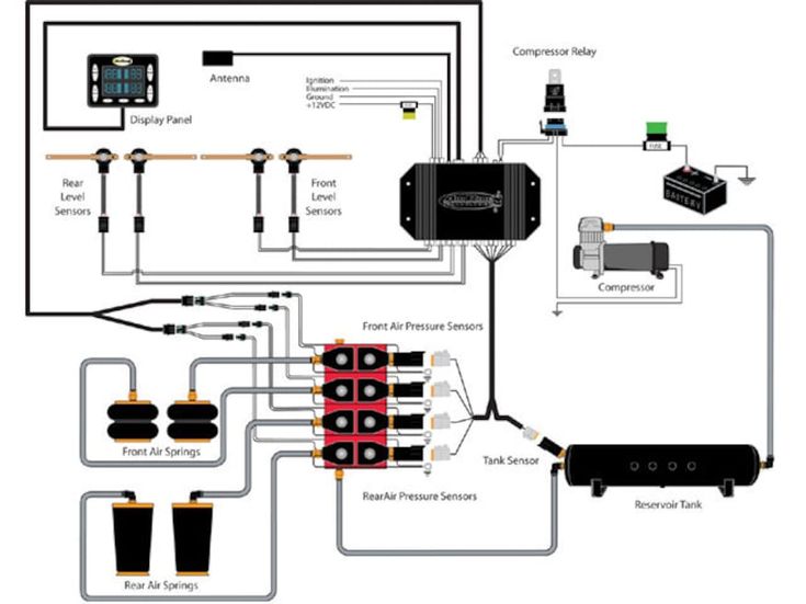
So, you're diving into the world of air ride suspension? Excellent choice. It’s a fantastic way to enhance your vehicle’s stance, improve ride quality, and even tackle challenging terrains. But before you start wrenching, understanding the wiring is absolutely crucial. This article will be your comprehensive guide to deciphering air ride suspension wiring diagrams, empowering you to confidently install, troubleshoot, or simply understand your system. We'll cover everything from the fundamental components to practical troubleshooting tips, all presented in a clear and accessible way.
Purpose of Understanding the Air Ride Suspension Wiring Diagram
Why bother dissecting these diagrams? Several reasons. First, if you're tackling a DIY air ride installation, the wiring diagram is your blueprint. It dictates how all the electronic components connect, ensuring everything functions correctly. Second, when things go wrong – and they sometimes do – a wiring diagram is your troubleshooting bible. It allows you to trace circuits, identify faulty connections, and isolate the problem. Finally, even if you're not actively working on your system, understanding the wiring diagram gives you a deeper appreciation for how your air ride suspension functions and allows you to communicate more effectively with professional installers or repair shops.
Key Specs and Main Parts of an Air Ride System
Let's familiarize ourselves with the major players in an air ride system. The wiring diagram will often represent these components symbolically, so knowing what they are is paramount:
- Air Compressor: The heart of the system. It compresses air, filling the air tank. Expect to see wiring for power, ground, and often a pressure sensor or relay.
- Air Tank: Stores the compressed air, ready to be distributed to the air springs. While the tank itself isn't wired, any pressure sensors or gauges connected to it will be.
- ECU (Electronic Control Unit): The brain of the operation. This controls the entire air ride system, managing pressure, height, and often offering preset ride heights. Wiring will include power, ground, sensor inputs, and valve outputs.
- Valve Manifold: A collection of solenoid valves that control the flow of air to each individual air spring. The diagram will show wiring for each valve, typically labeled for front left (FL), front right (FR), rear left (RL), and rear right (RR).
- Air Springs (Air Bags): The inflatable bladders that replace traditional coil springs. They receive air from the valve manifold. No direct wiring to the air springs themselves.
- Height Sensors: Measure the distance between the chassis and the suspension components. These sensors provide the ECU with crucial data for maintaining the desired ride height. Wiring includes power, ground, and a signal wire. These are often potentiometers or ultrasonic sensors.
- Pressure Sensors: Monitor the air pressure in the tank, lines, and sometimes individual air springs. Wiring is similar to height sensors – power, ground, and signal.
- Switches/Controller: The user interface for adjusting ride height. Wiring connects to the ECU.
- Fuses and Relays: Critical for circuit protection and controlling high-current components like the compressor. The diagram will clearly indicate their location and function.
Symbols: Decoding the Wiring Diagram
Wiring diagrams use standardized symbols to represent components and connections. Here's a breakdown of common symbols you'll encounter:
- Lines: Represent wires. Solid lines usually indicate positive wires, while dashed lines often denote ground wires. Different colors are used to distinguish between circuits.
- Colors: Standard wire colors like red (power), black (ground), and yellow (switched power) are frequently used. Consult the diagram's legend for specific color coding. It might denote each color, e.g., "BLU – Blue", "GRN – Green".
- Resistors: Zigzag lines represent resistors, which limit current flow.
- Capacitors: Two parallel lines symbolize capacitors, which store electrical energy.
- Diodes: A triangle with a line at its point represents a diode, which allows current to flow in only one direction.
- Relays: A coil with a switch mechanism. The coil, when energized, closes or opens the switch contacts. The diagram will show the coil terminals and the switch terminals.
- Fuses: A wavy line within a rectangle represents a fuse, a safety device that breaks the circuit if the current exceeds a certain level.
- Ground: Several symbols are used for ground, including a series of downward-pointing lines or a horizontal line with short vertical lines descending from it.
- Connectors: Circles or squares where wires connect. Numbered pins within the connector are often indicated.
It's crucial to refer to the legend of the specific wiring diagram you're using. The legend will provide the definitions of all the symbols and color codes used in that diagram.
How It Works: Tracing the Circuit
Let’s consider a simplified example: the air compressor circuit. The wiring diagram would likely show the following:
- A 12V power source (battery).
- A fuse to protect the circuit.
- A relay, controlled by the ECU.
- The air compressor.
- A ground connection.
The ECU monitors the air pressure in the tank via a pressure sensor. When the pressure drops below a certain threshold, the ECU activates the relay. The relay then closes the circuit, allowing power to flow to the air compressor, which starts pumping air into the tank. Once the desired pressure is reached, the ECU deactivates the relay, stopping the compressor.
Tracing a signal through the diagram involves starting at the source (e.g., the ECU output pin for the compressor relay) and following the wire to the destination (the relay coil). Pay attention to any components along the way, such as fuses or connectors.
Real-World Use: Basic Troubleshooting Tips
Wiring diagrams are invaluable when troubleshooting. Here are some common scenarios:
- Compressor not turning on: Check the fuse, relay, and wiring connections. Use a multimeter to verify that power is reaching the compressor. Consult the wiring diagram to identify the specific wires to test.
- Height sensors giving incorrect readings: Verify the wiring connections to the ECU. Check the sensor's power and ground. Use a multimeter to measure the sensor's output signal and compare it to the expected range.
- Air leak: While a wiring diagram won't directly show air leaks, it can help you identify faulty valve solenoids. If a valve is stuck open, it might be due to a wiring issue or a faulty solenoid.
When troubleshooting, always work methodically. Start with the simplest possible cause and work your way up. Refer to the wiring diagram frequently to ensure you're testing the correct circuits.
Safety: Highlighting Risky Components
Working with electrical systems always carries some risk. Here are a few key safety points to remember:
- Disconnect the battery: Before working on any wiring, disconnect the negative terminal of the battery. This prevents accidental shorts and electrical shocks.
- Use proper tools: Use insulated tools designed for automotive electrical work.
- Work in a well-lit area: Good visibility is essential for safe and accurate work.
- Be aware of high-current circuits: The compressor circuit, in particular, can carry a significant amount of current. Exercise caution when working with these circuits.
- Fuses are your friend: Never bypass a fuse. Fuses are designed to protect the wiring and components from damage.
Always consult a qualified professional if you're unsure about any aspect of the wiring. Improper wiring can damage your vehicle and pose a safety hazard.
Conclusion
Understanding air ride suspension wiring diagrams might seem daunting at first, but with a systematic approach and a good understanding of the components, you can confidently tackle installations, repairs, and troubleshooting. Remember to always prioritize safety and consult the wiring diagram specific to your air ride system.
We've compiled a generic air ride suspension wiring diagram that will offer insight into the systems we've discussed. Click below to download the image and save it for your reference:
Click here to download the example Air Ride Suspension Wiring Diagram