Wiring Diagram For Alternator With External Regulator
Wiring diagrams for alternators with external regulators might seem like relics of the past, but understanding them remains crucial for several reasons. Whether you're working on a classic car, upgrading a charging system, troubleshooting electrical issues, or simply expanding your automotive knowledge, grasping the principles behind these circuits can save you time, money, and potential headaches. This guide provides a detailed look at alternator wiring diagrams with external regulators, designed for experienced DIYers ready to tackle more complex automotive tasks.
Purpose of Understanding the Wiring Diagram
Why bother with a wiring diagram? Here are a few compelling reasons:
- Repair and Restoration: Many older vehicles still on the road utilize external voltage regulators. If you're restoring a classic or maintaining a vintage ride, understanding these diagrams is essential for troubleshooting charging system problems.
- Custom Modifications: When upgrading your vehicle's electrical system (e.g., installing a high-output alternator), knowing how the regulator interacts with the alternator is vital for proper integration. This could involve modifying existing wiring or creating new circuits.
- Troubleshooting: A faulty charging system can leave you stranded. With a wiring diagram, you can systematically trace circuits, identify broken wires, short circuits, or failing components.
- Educational Value: Even if your modern car doesn't use an external regulator, learning the principles behind it solidifies your understanding of how charging systems work in general. This foundational knowledge is invaluable for diagnosing all sorts of electrical problems.
Key Specs and Main Parts
Before diving into the diagram, let's identify the critical components and their specifications:
Alternator
The alternator is the heart of the charging system, converting mechanical energy from the engine into electrical energy. Key specs include:
- Voltage Output: Typically 13.5 - 14.5 volts.
- Current Output (Amperage): Varies depending on the alternator model (e.g., 60 amps, 100 amps, etc.). Higher amperage alternators are used when there are more electric devices that need power, such as heavy duty off-road lights and big audio systems.
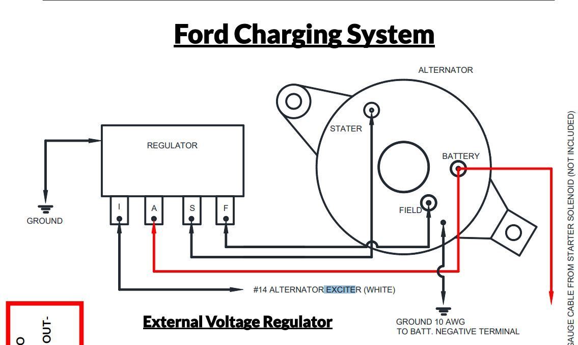
- Terminal Identification: Usually labeled with letters like 'BAT,' 'FLD' (or 'F'), 'STA' (or 'S'), and sometimes a ground symbol.
External Voltage Regulator
The external voltage regulator controls the alternator's output voltage, preventing overcharging and protecting the battery and other electrical components. Key specs and features include:
- Voltage Setting: Usually around 14 volts. This is a fixed value for most external regulators, but some adjustable types are available.
- Terminal Identification: Terminals are typically labeled with letters or numbers, such as 'F' (Field), 'I' (Ignition), 'A' (or 'S' for sense), and 'B' (Battery).
- Solid-State vs. Electro-Mechanical: Older systems used electro-mechanical regulators (relays and contact points), while newer aftermarket regulators are often solid-state for better reliability and accuracy.
Battery
The battery stores electrical energy and provides it to the starter and other accessories when the engine isn't running. Key specs:
- Voltage: Typically 12 volts (12.6V when fully charged).
- Amp-Hour (Ah) Rating: Indicates the battery's capacity to deliver current over time.
Wiring Harness
The network of wires connecting the components. Wire gauge (thickness) is crucial for handling the current flow. Thicker wires are required for higher amperage circuits.
Symbols and Color Codes
Wiring diagrams use standardized symbols and color codes to represent components and connections. Here's a breakdown:
- Solid Lines: Represent wires.
- Dashed Lines: May indicate shielded wires or grounds.
- Circles: Can represent connectors or splices. A filled circle often denotes a direct connection.
- Rectangles: Typically represent components like the regulator, alternator, or fuses.
- Ground Symbol (⏚): Indicates a connection to the vehicle's chassis, providing a return path for current.
- Color Codes:
- Red: Usually indicates power from the battery (always hot).
- Black: Typically represents ground.
- Blue, Green, Yellow, White: Used for various circuits and signals. The specific color coding can vary depending on the vehicle manufacturer. Refer to the specific diagram for your vehicle.
Important: Always refer to the specific wiring diagram for your vehicle or component. General color codes are helpful but not always consistent.
How It Works
The alternator with an external regulator works by controlling the current flow to the alternator's field winding. Here's the basic principle:
- Engine Starts: The engine turns the alternator's rotor.
- Field Excitation: The voltage regulator senses the battery voltage. If it's low, the regulator allows current to flow from the ignition switch (or another power source) through the field winding of the alternator. This creates a magnetic field within the alternator.
- Voltage Generation: The rotating magnetic field induces a voltage in the alternator's stator windings. This voltage is rectified (converted from AC to DC) and supplied to the battery.
- Voltage Regulation: As the battery voltage rises, the voltage regulator gradually reduces the current flowing to the field winding. This weakens the magnetic field, reducing the alternator's output voltage.
- Feedback Loop: The regulator constantly monitors the battery voltage and adjusts the field current to maintain a stable output voltage (around 14 volts). This creates a closed-loop feedback system.
In essence, the external regulator acts as a sophisticated switch, controlling the alternator's output based on the battery's state of charge. Older electro-mechanical regulators achieve this with vibrating contact points and relays, while modern solid-state regulators use transistors and integrated circuits for more precise control.
Real-World Use: Basic Troubleshooting Tips
Here's how you can use a wiring diagram to troubleshoot common issues:
- No Charging:
- Check Fuses: Blown fuses are a common cause. Use the diagram to locate the fuses in the charging circuit and test them with a multimeter.
- Voltage Regulator Test: With the engine running, check for voltage at the regulator's terminals (I, F, A, B). If you don't have voltage on the 'I' (ignition) terminal, then the regulator isn't getting power. If you have voltage at the regulator, but not at the alternator's field terminal, then the regulator may be faulty.
- Alternator Field Winding: Disconnect the field wire from the regulator and use an ohmmeter to check the resistance of the field winding. An open circuit (infinite resistance) indicates a broken winding.
- Ground Connections: Ensure all ground connections are clean, tight, and free of corrosion. Poor grounds can cause voltage drops and erratic charging.
- Overcharging:
- Voltage Regulator: This is almost always a faulty voltage regulator. Replace it with a new one.
- Sense Wire: If the regulator has a "sense" wire (often labeled 'S'), make sure it's properly connected to a point close to the battery. A bad sense connection can cause the regulator to misread the battery voltage and overcharge it.
- Battery Draining:
- Diode Test: A shorted diode in the alternator can cause a current drain even when the engine is off. Use a multimeter to test the diodes in the alternator.
- Parasitic Draw: If the alternator isn't the cause, there could be other circuits drawing current when the vehicle is off. Perform a parasitic draw test to identify the source of the drain.
Safety Precautions
Working with automotive electrical systems can be dangerous. Here are some crucial safety tips:
- Disconnect the Battery: Always disconnect the negative battery cable before working on any electrical components. This prevents accidental short circuits.
- Wear Safety Glasses: Protect your eyes from sparks and debris.
- Use Insulated Tools: Avoid using metal tools that could create a short circuit.
- Avoid Working Alone: Have someone nearby in case of an emergency.
- Be Careful Around the Alternator Terminals: The 'BAT' terminal is connected directly to the battery and can deliver a powerful shock. Never touch this terminal while the engine is running.
- Proper Wiring: Always use the correct wire gauge for the circuit. Undersized wires can overheat and cause a fire.
Disclaimer: Automotive electrical systems can be complex. If you are not comfortable working on them, consult a qualified mechanic. Improper repairs can damage your vehicle and create a safety hazard.
We have a detailed, downloadable wiring diagram file to further assist with your understanding. Access to the wiring diagram would provide you with a comprehensive visual representation of the electrical connections and components. This resource can significantly aid in troubleshooting, repair, and modification tasks.