Wiring Diagram For Alternator With External Voltage Regulator
So, you're diving into the fascinating world of alternator wiring with an external voltage regulator? Excellent! This article is your guide to understanding these systems, whether you're troubleshooting a vintage ride, hot-rodding a classic, or simply expanding your automotive knowledge. We'll break down the wiring diagram, explain the components, and give you some real-world tips to keep you safe and successful. We have prepared a detailed wiring diagram for you. The download link is at the end of the article.
Purpose: Why This Matters
Why bother understanding alternator wiring with an external voltage regulator? Several reasons:
- Repairing Classic Vehicles: Many older cars and trucks, particularly those from the 60s and 70s, used these systems. Diagnosing and repairing charging issues requires understanding the wiring.
- Custom Builds and Modifications: If you're building a custom car or modifying an existing one, you might encounter or choose to use an external regulator setup.
- Educational Value: Understanding the basics of this system will help you to learn more about electrical systems in all vehicles.
- Troubleshooting Charging Issues: If your battery isn't charging properly, or the battery light is on, this knowledge is invaluable.
Key Specs and Main Parts
Before we dive into the diagram, let's define the key players:
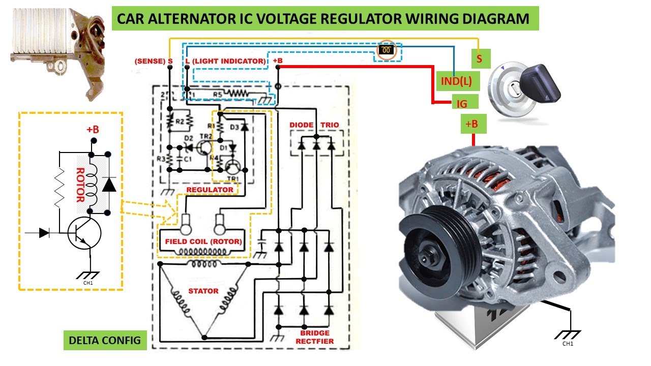
- Alternator: The heart of the system. Its job is to convert mechanical energy from the engine (via a belt and pulley) into electrical energy to charge the battery and power the vehicle's electrical systems. Internally, it contains a rotor, stator, rectifier diodes, and a fan for cooling.
- External Voltage Regulator: This is the brains of the operation. It monitors the battery voltage and controls the amount of field current sent to the alternator's rotor. By regulating the field current, it controls the alternator's output voltage, preventing overcharging and maintaining a stable voltage. Older units were often electromechanical (with points), while newer replacements are usually solid-state.
- Battery: The energy storage device. It provides power to start the engine and serves as a buffer for the electrical system.
- Ignition Switch: Provides switched power to various circuits, including the voltage regulator.
- Ammeter or Voltmeter: Indicates the charging status of the battery. An ammeter shows the current flow (charge or discharge), while a voltmeter shows the battery voltage. Many systems now use the battery light in the dashboard to indicate charging system status.
- Wiring Harness: The network of wires connecting all the components.
Symbols: Deciphering the Diagram
Understanding the symbols in a wiring diagram is crucial. Here are some common ones you'll encounter in an alternator with external regulator diagram:
- Solid Lines: Represent wires. The thickness of the line *usually* (but not always) indicates the wire gauge (thicker line = thicker wire).
- Dashed Lines: Often indicate wires that are shielded, or are part of a module and may not be individual, easily accessible wires.
- Color Codes: Each wire is assigned a color. For example, a red wire is often used for battery power, while a black wire is used for ground. Color codes vary between manufacturers, so always consult the specific diagram for your vehicle.
- Ground Symbol: Looks like an upside-down Christmas tree. Indicates a connection to the vehicle's chassis, which serves as the ground path.
- Battery Symbol: Usually depicted as a series of alternating long and short lines, representing the battery's cells.
- Alternator Symbol: Varies, but often includes a circle with an "A" inside, or a symbol representing a generator.
- Voltage Regulator Symbol: Also varies, but often resembles a small box with connections indicated.
- Connectors: Shown as circles or squares where wires connect.
- Fuses: Depicted as a squiggly line inside a rectangle, or a simple rectangle with the amperage rating indicated.
- Resistors: A zig-zag line.
- Diodes: Triangle with a line on one side.
Common Wire Colors and Their Meanings (General Guidelines)
While color codes vary, here's a common pattern:
- Red: Battery positive (+)
- Black: Ground (-)
- Yellow: Often used for alternator output.
- Blue: Ignition switched power
- Green: Can be used for various signals, but often associated with lighting circuits.
- White: Often used for lighting or sensor signals.
Important: Always refer to the specific wiring diagram for your vehicle to confirm the color codes and their functions. Never assume!
How It Works: The Flow of Electricity
Here's the basic flow of electricity in an alternator system with an external voltage regulator:
- Ignition On: When the ignition switch is turned on, power is supplied to the voltage regulator.
- Voltage Regulator Activation: The regulator monitors the battery voltage. If the voltage is low, the regulator allows current to flow through the field winding (rotor) inside the alternator.
- Field Winding Excitation: The field winding creates a magnetic field.
- Alternator Output: As the engine turns the alternator's rotor, the rotating magnetic field induces a voltage in the stator windings.
- Rectification: The AC voltage produced by the stator is converted to DC voltage by rectifier diodes inside the alternator.
- Charging the Battery: The DC voltage from the alternator is then used to charge the battery and power the vehicle's electrical system.
- Voltage Regulation: As the battery voltage rises, the voltage regulator gradually reduces the amount of current flowing through the field winding. This reduces the alternator's output voltage, preventing overcharging.
- Feedback Loop: The voltage regulator constantly monitors the battery voltage and adjusts the field current accordingly, maintaining a stable voltage output.
Real-World Use: Troubleshooting Tips
Here are some basic troubleshooting tips you can use with the wiring diagram:
- No Charging: If the battery isn't charging, check the following:
- Battery Voltage: Ensure the battery is good and properly charged to begin with.
- Belt Tension: Make sure the alternator belt is properly tensioned. A loose belt will cause the alternator to slip, reducing its output.
- Fuse: Check the fuse for the voltage regulator and/or alternator field circuit. A blown fuse will prevent the system from operating.
- Wiring Connections: Inspect all wiring connections for corrosion, looseness, or damage. Pay particular attention to the connections at the alternator, voltage regulator, battery, and ground points. Clean and tighten any suspect connections.
- Voltage Regulator: A faulty voltage regulator is a common cause of charging problems. If possible, test the regulator using a multimeter or a dedicated voltage regulator tester.
- Alternator: If the voltage regulator is good, the alternator itself may be faulty. Have the alternator tested at an auto parts store.
- Overcharging: If the battery is constantly overcharging, check the following:
- Voltage Regulator: A faulty voltage regulator is the most likely cause of overcharging. Replace the regulator with a new one.
- Ground Connections: Poor ground connections can sometimes cause overcharging. Ensure all ground connections are clean and tight.
- Battery Light Stays On: If the battery light on the dashboard stays on, it indicates a charging system problem. Follow the troubleshooting steps for "No Charging."
Safety: Handle with Care
Working with automotive electrical systems can be dangerous. Here are some safety precautions to keep in mind:
- Disconnect the Battery: Always disconnect the negative (-) battery cable before working on any electrical components. This will prevent accidental shorts and electrical shocks.
- Wear Safety Glasses: Protect your eyes from sparks and debris.
- Use Insulated Tools: Use tools with insulated handles to prevent electrical shock.
- Avoid Working in Wet Conditions: Water can conduct electricity, increasing the risk of shock.
- Be Careful Around the Alternator: The alternator can get very hot during operation. Allow it to cool down before touching it. Also, be careful of the moving belt and pulley.
- Capacitors in the System: Be aware that some voltage regulators or other modules may contain capacitors that can hold a charge even after the battery is disconnected. Discharge these capacitors before working on the circuit.
- Never Directly Ground the Field Terminal: Doing so can severely damage the alternator and voltage regulator.
Warning: The alternator output wire is directly connected to the battery. A short circuit on this wire can cause a fire. Use extreme caution when working with this wire.
Ready to Dive Deeper?
We've covered the basics, but there's always more to learn. To help you even further, we have prepared a detailed wiring diagram for an alternator with an external voltage regulator. This diagram includes clear labels, color-coded wires, and a detailed explanation of each component. It is very useful for diagnostics and repairs.
You can download the wiring diagram here: Download Wiring Diagram
Remember, this article is a guide, but always refer to the specific wiring diagram for your vehicle for accurate information. Good luck, and happy wrenching!