
Wiring Diagram For Auto Gauge Tachometer
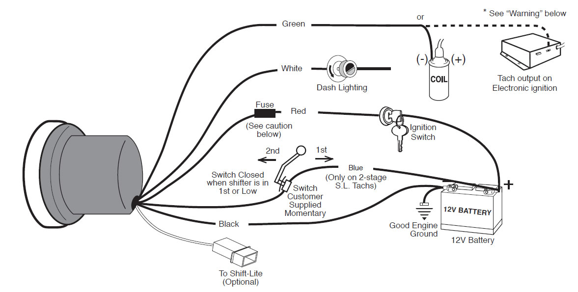
So, you're looking to wire up an aftermarket tachometer? Excellent choice! Whether you're replacing a faulty factory unit, adding a tach to a car that never had one, or just wanting to upgrade to something with more style and features, understanding the wiring is absolutely crucial. This article breaks down the typical wiring diagram for an auto gauge tachometer, giving you the knowledge to tackle this project with confidence. We'll cover the purpose of each wire, explain common symbols, and offer some real-world troubleshooting tips. Plus, we have a downloadable wiring diagram that complements this explanation – more on that later!
Why This Diagram Matters
A clear understanding of the tachometer wiring diagram is essential for several reasons:
- Installation: Correctly connecting the tachometer to your vehicle's electrical system is the first step. A wrong connection can lead to the tach not working, inaccurate readings, or even damage to the tachometer or your vehicle's electrical system.
- Troubleshooting: If your tachometer isn't behaving as it should (erratic readings, no readings at all, etc.), a wiring diagram allows you to systematically check each connection and rule out wiring issues as the cause.
- Modification: If you're customizing your vehicle's instrumentation or adding aftermarket gauges, understanding the wiring diagram allows you to integrate the tachometer seamlessly into your existing system.
- Learning: Even if you don't need to install or troubleshoot a tachometer right now, studying the wiring diagram is a fantastic way to deepen your understanding of automotive electrical systems in general.
Key Specs and Main Parts of a Tachometer System
Before diving into the diagram itself, let's cover the basics. A tachometer, or tach, measures the rotational speed of an engine's crankshaft, typically displayed in revolutions per minute (RPM). Here are some important components and specifications to be aware of:
- Tachometer Gauge: This is the display unit itself, housing the needle, scale, and often other features like shift lights or digital displays.
- Signal Wire: This wire receives the RPM signal from the engine. It's often connected to the negative (-) side of the ignition coil in older vehicles or to the ECU (Engine Control Unit) in newer vehicles.
- Power Wire: Provides the tachometer with the necessary voltage to operate, usually 12V DC.
- Ground Wire: Creates a return path for the electrical current, completing the circuit. A good, clean ground is crucial for accurate readings.
- Lighting Wire (Optional): This wire connects to the vehicle's lighting system, allowing the tachometer's illumination to dim or brighten with the headlights.
- Shift Light (Optional): Some tachometers include a shift light, which illuminates when the engine reaches a pre-set RPM, signaling the driver to shift gears.
- Cylinder Selection (For Some Tachometers): Older tachometers might have a switch or setting to adjust for the number of cylinders in your engine. This ensures accurate RPM readings. Modern ones typically auto-calibrate.
Understanding Wiring Diagram Symbols
Wiring diagrams use standardized symbols to represent different components and connections. Here's a breakdown of the common symbols you'll encounter in a tachometer wiring diagram:
- Solid Lines: Represent wires. The thickness of the line might indicate the wire gauge (thicker lines for higher current).
- Dashed Lines: Sometimes used to indicate wires that are optional or present only in certain configurations.
- Circles or Dots: Indicate connection points where wires are joined together.
- Ground Symbol: Usually a series of horizontal lines getting progressively shorter, representing a connection to the vehicle's chassis (ground).
- Battery Symbol: Represents the vehicle's battery, typically with a (+) and (-) symbol to indicate polarity.
- Fuse Symbol: A zigzag line inside a rectangle, indicating a fuse for circuit protection.
- Resistor Symbol: A zigzag line, representing a resistor used to limit current flow.
- Coil Symbol: Indicates the ignition coil.
- Switch Symbol: Shows a switch in either the open (off) or closed (on) position.
Wire Colors: Wire colors are often indicated by abbreviations (e.g., RED, BLK, GRN, BLU). While not always consistent across all manufacturers, there are some common conventions. Red is typically used for positive power, black for ground, and other colors for signal or accessory wires. Always refer to the specific wiring diagram for your tachometer to confirm the color coding.
How It Works: A Simplified Explanation
Here's a simplified explanation of how a typical auto gauge tachometer wiring works:
- Power (12V DC): The power wire from the tachometer is connected to a switched 12V DC source in the vehicle. This means the tachometer only receives power when the ignition is turned on. This connection usually runs through a fuse for protection.
- Ground: The ground wire is connected to a clean, reliable ground point on the vehicle's chassis. A poor ground can cause all sorts of issues, from inaccurate readings to complete failure.
- Signal: The signal wire is connected to a source that provides an electrical pulse proportional to the engine's RPM. This is the trickiest part, as the connection point varies depending on the vehicle's ignition system. In older cars with conventional ignition systems, this is often the negative (-) terminal of the ignition coil. In newer cars with electronic ignition or coil-on-plug systems, the signal wire is typically connected to a specific pin on the ECU that outputs the RPM signal. Using the correct connection is crucial.
- Lighting (Optional): If the tachometer has a lighting wire, it's connected to the vehicle's lighting circuit, typically the wire that powers the dashboard lights. This allows the tachometer's illumination to dim or brighten with the headlights.
Real-World Use: Basic Troubleshooting Tips
Having problems with your tachometer? Here are a few basic troubleshooting tips based on the wiring:
- No Reading at All:
- Check the power wire for voltage using a multimeter. Is it getting 12V when the ignition is on?
- Verify the ground connection. Is it clean and secure? Use a multimeter to check for continuity between the ground wire and the vehicle's chassis.
- Inspect the fuse for the tachometer circuit. Is it blown?
- Erratic Readings:
- Double-check the signal wire connection. Is it securely connected to the correct source?
- Consider a bad ground. A loose or corroded ground connection can cause erratic readings. Clean and tighten the ground connection.
- If the tachometer has a cylinder selection switch, make sure it's set correctly for your engine.
- Incorrect RPM Reading:
- Verify the signal wire connection point. For newer cars, make sure you have the correct wire from the ECU.
- If the tachometer has a cylinder setting, it may be incorrect.
Safety First!
Working with automotive electrical systems can be dangerous if you're not careful. Here are a few important safety precautions:
- Disconnect the Battery: Before working on any electrical circuits in your vehicle, always disconnect the negative (-) battery cable. This prevents accidental shorts and potential shocks.
- Be Careful Around the Ignition Coil: The ignition coil can generate high voltage, even with the ignition off. Avoid touching the terminals of the ignition coil with your bare hands.
- Use a Multimeter: A multimeter is an essential tool for troubleshooting electrical problems. Learn how to use it safely and effectively.
- Consult a Professional: If you're not comfortable working with automotive electrical systems, consult a qualified mechanic. It's better to be safe than sorry! Especially when dealing with the ECU and associated wiring, improper connections can cause serious damage.
This article provides a solid foundation for understanding auto gauge tachometer wiring diagrams. However, every vehicle and tachometer model is different. Always refer to the specific wiring diagram for your vehicle and tachometer before starting any work. We have a sample wiring diagram that includes color codes, connection points, and common symbols. You can download it here. This diagram complements the information provided in this article and can be a valuable resource during your installation or troubleshooting process. Good luck, and remember to work safely!