
Wiring Diagram For Blower Motor Resistor
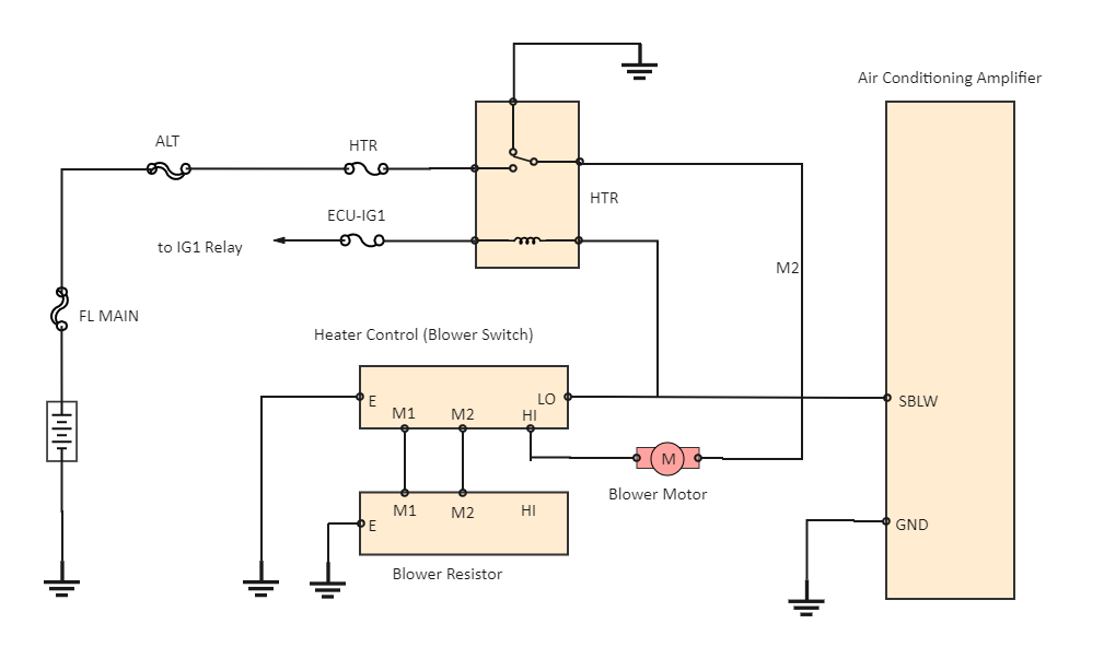
Let's talk about blower motor resistor wiring diagrams. Understanding them is crucial whether you're tackling a faulty climate control system, customizing your car's electricals, or just trying to get a deeper understanding of how your vehicle works. Think of this as your roadmap to navigating the often-overlooked world of blower motor resistor circuits. We're going to break down what these diagrams represent, how to read them, and how to use them for troubleshooting and repairs. Consider this guide a useful reference for any seasoned DIYer.
Purpose: Why You Need to Understand This
Why bother learning about blower motor resistor wiring diagrams? Simple: it empowers you to fix problems yourself, saving you money and time. Here are a few key reasons:
- Repairing a faulty blower motor: A common symptom is that your blower motor only works on high speed, or doesn't work at all. The resistor is a prime suspect.
- Upgrading or modifying your climate control system: If you're adding aftermarket components, you'll need to understand the existing wiring to integrate them correctly.
- Electrical troubleshooting: A wiring diagram provides a logical framework for diagnosing electrical issues related to the blower motor circuit.
- Educational purposes: For car enthusiasts who want to understand the inner workings of their vehicles, this is a valuable piece of the puzzle.
Key Specs and Main Parts
Before diving into the diagram, let's define the essential components and specifications you'll encounter. A typical blower motor resistor circuit includes the following:
- Blower Motor: The electric motor that drives the fan, circulating air through the heating and air conditioning system. These are typically DC motors.
- Blower Motor Resistor (or Resistor Block): This component controls the blower motor's speed. It consists of a set of resistors with different resistance values. Each resistor corresponds to a specific fan speed setting (low, medium-low, medium-high, etc.). Some vehicles use a blower motor control module which is a more complex electronic device that performs the same function.
- Blower Motor Switch (or Fan Speed Selector): The switch on your dashboard that allows you to select the desired fan speed.
- Fuses and Relays: Protective devices that safeguard the circuit from overcurrent and allow a low-current switch to control a high-current motor. A relay is essentially an electrically operated switch.
- Wiring Harness: The network of wires that connects all the components. These are often color-coded, which is critical for using the wiring diagram.
- Ground Connection: Provides a return path for the electrical current to the vehicle's chassis, completing the circuit. A bad ground is a frequent cause of blower motor issues.
Important Specifications:
- Voltage: Typically 12V DC in most vehicles. Make sure to verify the voltage of *your* vehicle with a multimeter.
- Resistance Values: Each resistor within the resistor block will have a specific resistance value, measured in Ohms (Ω). These values are critical for proper fan speed operation. These values can often be found on the resistor itself, or within the vehicle's service manual.
- Wire Gauge (AWG): The thickness of the wires in the harness. Using the correct wire gauge is crucial for handling the current draw of the blower motor.
- Fuse Rating: The maximum current that the fuse can handle before it blows, protecting the circuit from overcurrent.
Symbols: Decoding the Wiring Diagram
Wiring diagrams use standardized symbols to represent electrical components. Here are some common symbols you'll encounter in a blower motor resistor circuit diagram:
- Straight Lines: Represent wires. Thicker lines sometimes indicate wires with a larger gauge.
- Dots at Wire Intersections: Indicate a connection between wires. If wires cross without a dot, they are not connected.
- Resistor Symbol (Zig-zag line): Represents a resistor. The value of the resistor in Ohms (Ω) is usually indicated next to the symbol.
- Ground Symbol (Downward facing triangle or stacked horizontal lines): Indicates a connection to the vehicle's chassis ground.
- Fuse Symbol (S-shaped line inside a rectangle or a straight line with a bump): Represents a fuse. The amperage rating (e.g., 20A) is usually indicated.
- Switch Symbol (A break in the line with a lever): Represents a switch. Different switch positions are shown as different connections.
- Motor Symbol (Circle with an "M" inside): Represents the blower motor.
- Relay Symbol (Coil and a set of contacts): Represents a relay. The diagram will show the coil, the normally open (NO) contact, and the normally closed (NC) contact (if present).
Color Codes:
Wiring diagrams also use color codes to identify individual wires. Common color codes include:
- BLK: Black (usually ground)
- RED: Red (usually power)
- BLU: Blue
- GRN: Green
- YEL: Yellow
- WHT: White
- BRN: Brown
- Combinations like GRN/WHT (Green with a White stripe) are also common.
The color codes are crucial for tracing wires and ensuring you're working on the correct circuit. Always double-check the wire color against the diagram before making any connections or disconnections.
How It Works: The Blower Motor Resistor Circuit in Action
The blower motor resistor circuit controls the speed of the blower motor by varying the amount of resistance in the circuit. When you select a low fan speed, the current flows through a resistor with a high resistance value. This high resistance reduces the voltage reaching the blower motor, causing it to run at a slower speed. Conversely, when you select a high fan speed, the current flows through a resistor with a low resistance value (or bypasses the resistors entirely), allowing more voltage to reach the blower motor and run at a higher speed.
Here's a simplified breakdown:
- Power Source: Battery supplies power to the circuit.
- Fuse Protection: The fuse protects the circuit from overcurrent.
- Blower Motor Switch: The driver selects the desired fan speed.
- Resistor Block: Depending on the selected speed, the current flows through a specific resistor (or bypasses them).
- Blower Motor: The motor receives the appropriate voltage and spins at the corresponding speed.
- Ground: The current returns to the battery through the ground connection.
In many modern vehicles, the blower motor resistor is replaced by a blower motor control module. This module uses electronic components to regulate the voltage to the blower motor, providing more precise control and potentially improved efficiency.
Real-World Use: Basic Troubleshooting Tips
Using the wiring diagram, you can diagnose common blower motor problems:
- Blower motor only works on high speed: This usually indicates a faulty resistor block. The high-speed setting often bypasses the resistors entirely, so it still works even when the resistors are damaged. Use a multimeter to check the resistance of each resistor in the block. An open circuit (infinite resistance) indicates a failed resistor.
- Blower motor doesn't work at all: Check the fuse first! If the fuse is good, use a multimeter to check for voltage at the blower motor connector when the switch is in the "on" position. If there's no voltage, trace the circuit back towards the power source, checking for broken wires or faulty connections along the way.
- Blower motor works intermittently: This could be a loose connection, a corroded connector, or a failing blower motor. Inspect the wiring harness for any signs of damage or corrosion. Try wiggling the wires to see if the motor starts working.
- Blower motor runs slowly even on high: Check the ground connection! A poor ground can restrict the current flow, causing the motor to run sluggishly. Clean and tighten the ground connection. Also, confirm the battery voltage is correct, and that the motor itself is not worn out.
Safety: Handle with Care
Working with electrical systems can be dangerous. Here are some important safety precautions:
- Disconnect the Battery: Always disconnect the negative battery terminal before working on any electrical circuits. This prevents accidental shorts and electrical shocks.
- Use Proper Tools: Use insulated tools designed for electrical work.
- Be Aware of Airbag Systems: Airbag systems are sensitive to electrical changes. Consult your vehicle's service manual before working near airbag components.
- Handle Resistors with Caution: Resistors can get hot when current flows through them. Allow them to cool down before handling them.
- Avoid Working in Wet Conditions: Water conducts electricity. Avoid working on electrical systems in wet or damp environments.
- Be especially cautious with the blower motor control module. It may contain capacitors that can store a charge even after the battery is disconnected. Let the module sit for a few minutes before handling it.
Remember, if you're not comfortable working with electrical systems, it's best to consult a qualified mechanic. Working with electricity can be dangerous if you don't know what you're doing.
You now have a solid understanding of blower motor resistor wiring diagrams. This knowledge will empower you to tackle common climate control problems and gain a deeper understanding of your vehicle's electrical system. Keep this guide handy for future reference!
We have a sample wiring diagram file available for you to download. It provides a visual reference to complement the information in this article. Consider it another tool in your arsenal for DIY car repairs!