Wiring Diagram For Car Stereo System
Let's dive into the world of car stereo wiring diagrams. If you're an experienced DIYer, car enthusiast, or just someone who likes to tinker, understanding these diagrams is crucial. Whether you're upgrading your head unit, adding an amplifier, diagnosing a blown fuse, or simply trying to understand how your car's audio system is wired, a clear wiring diagram is your best friend. It's the roadmap to a successful and safe installation or repair, preventing costly mistakes and potential damage to your vehicle's electrical system.
Purpose of a Car Stereo Wiring Diagram
A car stereo wiring diagram is essentially a visual representation of the electrical connections within your car's audio system. Its main purposes are:
- Repair and Troubleshooting: When something goes wrong (no sound, blown fuses, etc.), the diagram helps you trace the circuit, identify the faulty component, and pinpoint the location of the problem.
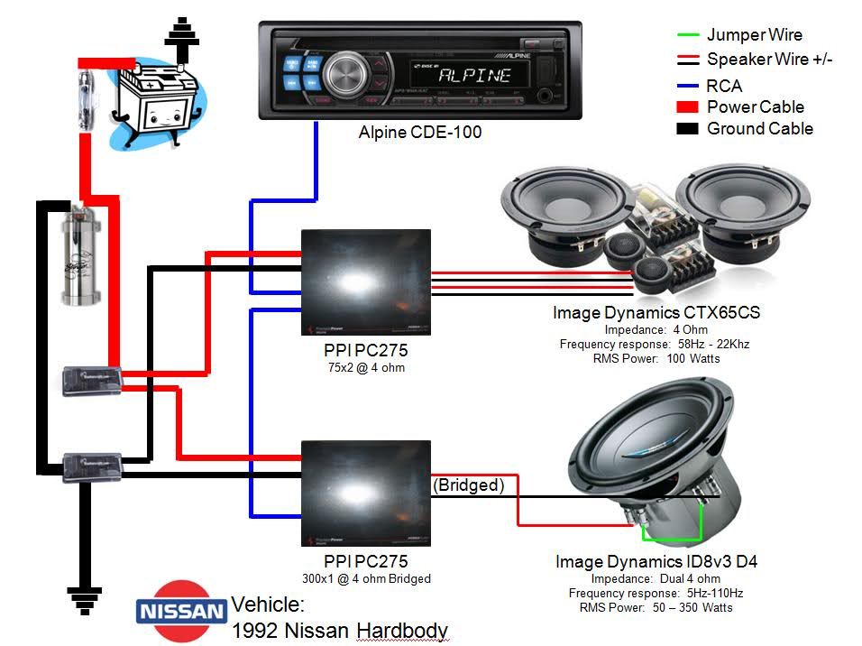
- Installation and Upgrades: Installing a new head unit, amplifier, speakers, or subwoofer becomes significantly easier and safer with a wiring diagram. It shows you exactly where each wire needs to be connected.
- System Understanding: Even if you're not planning any modifications, studying the diagram can give you a better understanding of how your car's audio system functions.
- Modification and Customization: For advanced modifications, like integrating aftermarket components or creating custom audio setups, a wiring diagram is indispensable.
Key Specs and Main Parts Depicted
Before we delve into the symbols, let's familiarize ourselves with the common components you'll find in a car stereo wiring diagram:
- Head Unit: The central control unit, often referred to as the receiver. It typically provides AM/FM radio, CD playback, Bluetooth connectivity, and other audio sources.
- Speakers: These convert electrical signals into audible sound. Diagrams will show front, rear, and potentially center channel speakers.
- Amplifier (Amp): Used to boost the audio signal from the head unit to the speakers, especially important for high-powered systems. Some head units have built-in amplifiers.
- Wiring Harness: A collection of wires bundled together with connectors, designed to plug directly into the back of the head unit. Aftermarket harnesses simplify installation.
- Fuses: Safety devices that protect the electrical circuits from overcurrent. Diagrams show the location of the fuses related to the audio system.
- Ground (Earth): Provides a return path for the electrical current. Usually connected to the car's chassis.
- Battery (Power Source): Provides the 12V DC power to the system.
- Antenna: Receives radio signals.
Understanding Wiring Diagram Symbols
Wiring diagrams use standardized symbols to represent different components and connections. It's essential to understand these symbols to accurately interpret the diagram.
- Lines: Represent wires. Different line styles (solid, dashed, dotted) may indicate different types of wires or connections. A thick line usually indicates a higher current carrying wire.
- Colors: Wires are often color-coded to make identification easier. Common colors include Red (power), Black (ground), Yellow (constant power), Blue (remote turn-on), and various colors for speaker wires. Check your specific vehicle's color codes, as they can vary.
- Circles/Dots: Indicate wire connections or splices. A filled circle often represents a permanent connection.
- Rectangles/Squares: Typically represent components like the head unit, amplifier, or fuse box.
- Speaker Symbol: A circle with a cone inside indicates a speaker. Some diagrams differentiate between tweeters and woofers.
- Ground Symbol: Usually represented by a series of descending lines or an upside-down triangle, indicating a connection to the vehicle's chassis.
- Fuse Symbol: A wavy line inside a rectangle, representing a fuse. The amperage rating is often indicated next to the symbol.
- Connector Symbol: Shows the location and type of connectors used to join wiring harnesses. This symbol may include a number indicating the pin count.
Crucially, pay attention to the abbreviations and notes on the diagram. These often provide additional information about wire gauges, connector types, and specific circuit functions. Knowing the difference between ACC (Accessory) and B+ (Battery Positive) is vital.
How It Works: The Electrical Flow
The car stereo system's operation is fairly straightforward: The battery provides power to the head unit (B+). When the car is turned on (ACC), the head unit powers up. The head unit then takes an audio signal from a source (radio, CD, Bluetooth) and amplifies it (either internally or through an external amplifier). Finally, the amplified audio signal is sent to the speakers, which produce sound. The ground connection completes the electrical circuit, allowing current to flow back to the battery.
A remote turn-on wire (usually blue or blue/white) from the head unit is used to activate an external amplifier. When the head unit is powered on, it sends a 12V signal through the remote wire, turning on the amplifier. This prevents the amplifier from drawing power when the head unit is off, saving battery life. The amplifier receives its main power from the B+ (battery positive) connection directly to the car battery, often through a heavy-gauge wire and a fuse near the battery.
The signal path starts at the head unit, travels through the amplifier (if present), and ends at the speakers. Understanding this flow is crucial for troubleshooting audio issues. For example, if you have no sound from one speaker, you can trace the wiring from the speaker back to the amplifier (if present) and then to the head unit to identify the point of failure.
Real-World Use: Basic Troubleshooting Tips
Here's how you can use a wiring diagram for basic troubleshooting:
- No Power to Head Unit: Check the fuse related to the head unit (refer to the diagram for location and amperage). Use a multimeter to verify voltage at the B+ and ACC wires. Ensure the ground connection is secure and making good contact with the chassis.
- No Sound from Speakers: Check the speaker wires for damage or loose connections. Use a multimeter to check for continuity (a complete circuit) between the head unit output and the speaker terminals. If an amplifier is used, check the remote turn-on wire and the amplifier's power connections.
- Blown Fuses: A frequently blown fuse indicates an overcurrent situation. Check the wiring for shorts (exposed wires touching the chassis). Ensure that the amplifier or head unit is not drawing more current than the fuse rating.
- Distorted Sound: Can be caused by damaged speakers, a faulty amplifier, or incorrect impedance matching. Refer to the diagram to verify the speaker wiring and impedance.
Safety Considerations
Working with car electrical systems involves inherent risks. Always follow these safety precautions:
- Disconnect the Battery: Before working on any electrical components, disconnect the negative terminal of the car battery to prevent short circuits and electrical shocks.
- Use Proper Tools: Use insulated tools designed for automotive electrical work.
- Avoid Working in Wet Conditions: Water and electricity are a dangerous combination.
- Identify High-Current Components: The amplifier power wire and the battery connections carry high current. Exercise extreme caution when working with these components. Ensure that the amplifier's power wire is properly fused near the battery.
- Double-Check Connections: Before reconnecting the battery, carefully double-check all wiring connections to ensure they are secure and properly insulated.
- Never cut or modify wiring without understanding its function.
Remember to consult your vehicle's repair manual for specific wiring diagrams and component locations. These diagrams are often vehicle-specific and can vary depending on the year, make, and model of your car.
We have a standard car stereo wiring diagram available for download to help you get started. It's a great reference tool, even if it doesn't perfectly match your specific vehicle. You can adapt the general principles explained here to your particular situation. Simply adapt the principles covered, to your vehicle's unique situation.