
Wiring Diagram For Chevy 350 Alternator
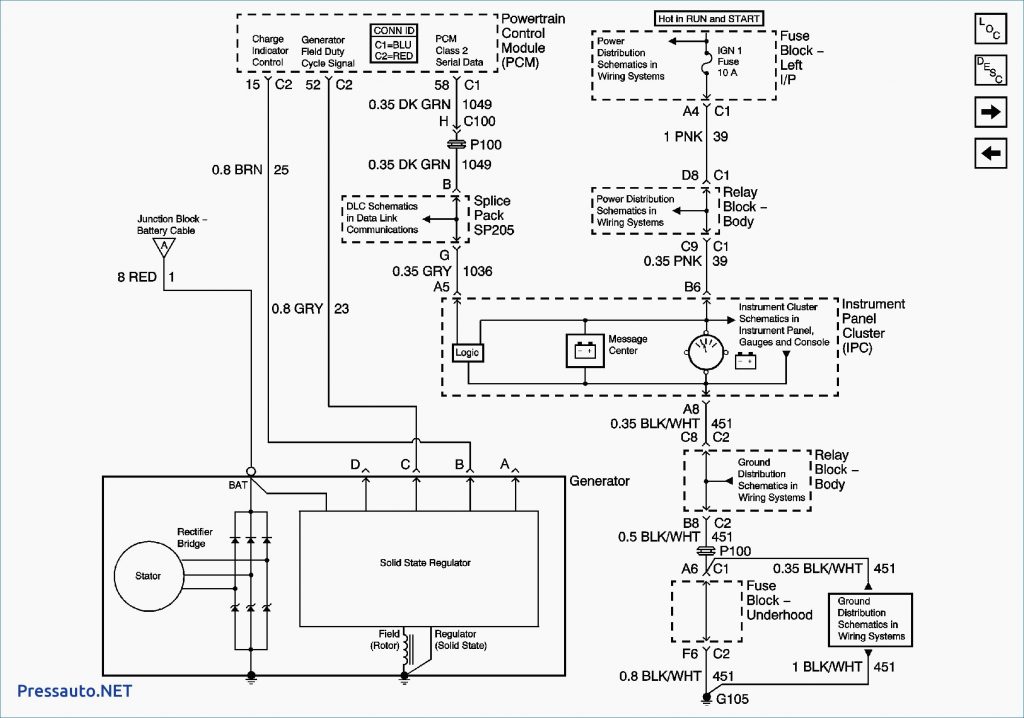
Understanding the wiring of your Chevy 350 alternator is crucial for a variety of reasons, from basic repairs and troubleshooting to more complex modifications like engine swaps or custom wiring harnesses. A clear wiring diagram is your roadmap to ensuring your charging system operates efficiently and reliably. This article will break down a typical Chevy 350 alternator wiring diagram, explain the key components, and provide practical troubleshooting advice.
Purpose of the Wiring Diagram
The primary purpose of an alternator wiring diagram is to provide a visual representation of how the alternator connects to the rest of the vehicle's electrical system. It shows the specific wires involved, their color codes, and the terminals they connect to on the alternator, voltage regulator (if applicable), battery, and other components. Having this diagram is essential for:
- Troubleshooting: Identifying breaks, shorts, or incorrect connections in the charging system.
- Repairs: Replacing damaged wiring or components correctly.
- Modifications: Integrating the alternator into a custom wiring harness or when performing an engine swap.
- Understanding: Gaining a deeper understanding of how your charging system works.
Without a diagram, you're essentially guessing, which can lead to further damage or even safety hazards. A diagram empowers you to diagnose issues accurately and perform repairs confidently.
Key Specs and Main Parts
Let's outline the key specifications and main parts typically found in a Chevy 350 alternator wiring system. While specific years and models might have slight variations, the fundamental principles remain the same.
Alternator Types
Most Chevy 350 engines utilize an internally regulated alternator, typically a Delco Remy 10SI or 12SI series. Older models might have an externally regulated alternator.
Key Parts
- Alternator: The main component that generates electrical power to charge the battery and power the vehicle's electrical accessories while the engine is running.
- Battery: Stores electrical energy and provides power to start the engine.
- Voltage Regulator: (Internally or externally mounted) Controls the alternator's output voltage to prevent overcharging the battery. Internally regulated alternators have the regulator inside the alternator housing.
- Wiring Harness: A collection of wires bundled together to connect various electrical components.
- Fuses/Fusible Links: Safety devices that protect the electrical system from overcurrents.
- Ground Wires: Provide a return path for current, ensuring proper circuit operation. A good ground is critical for the alternator to function correctly.
Typical Connections (Internally Regulated Alternator - Delco Remy Style)
- BAT Terminal: A large gauge wire (typically 10-12 gauge) connecting directly to the positive (+) terminal of the battery or the starter solenoid’s positive terminal, which is then connected to the battery. This is the main charging wire.
- Terminal 1 (or R terminal): Connects to the charging indicator light (idiot light) in the dashboard, and sometimes through a resistor. This provides a small amount of voltage to initially excite the alternator when the engine starts. If the light burns out, the alternator may not charge.
- Terminal 2 (or S terminal): This is a voltage sensing wire. It connects to a point in the electrical system where the voltage needs to be monitored, typically the positive (+) bus or connection point for accessories. This allows the alternator to adjust its output based on the actual voltage being seen by the vehicle's electrical system.
Symbols and Color Codes
Understanding the symbols and color codes used in a wiring diagram is vital for accurate interpretation. Here are some common elements:
- Solid Lines: Represent wires. The thickness of the line may indicate the wire gauge (thicker lines = larger gauge wires).
- Dashed Lines: May represent optional connections or internal wiring within a component.
- Color Codes: Wires are typically color-coded for identification. Common colors include Red (power), Black (ground), Orange, Blue, Yellow, and Green. The wiring diagram will have a legend identifying the specific color codes used.
- Symbols: Standard symbols represent components like alternators (typically a circle with "ALT" inside), batteries (parallel lines, one longer than the other), voltage regulators (a rectangle with pins), fuses (a squiggly line inside a rectangle), and ground points (a series of descending lines).
- Terminal Markings: Letters and numbers are used to identify specific terminals on components (e.g., BAT, 1, 2, S, R).
Example Color Codes (These can vary, always consult your specific diagram):
- Red: Battery positive (+)
- Black: Ground (-)
- Brown: Exciter/Indicator Light
- Blue: Voltage Sense
How It Works
Here’s a simplified explanation of how the Chevy 350 alternator charging system works, specifically with an internally regulated alternator:
- Starting the Engine: When the ignition is turned on, a small amount of current flows from the battery, through the charging indicator light (if present), and into Terminal 1 (or R) of the alternator. This provides initial excitation to the alternator's field windings.
- Alternator Activation: As the engine starts and the alternator begins to spin, the rotating rotor inside the alternator generates a magnetic field. This magnetic field induces a current in the stator windings.
- Voltage Regulation: The voltage regulator monitors the voltage at Terminal 2 (or S). If the voltage is low, the regulator increases the current flowing through the rotor windings, increasing the alternator's output. If the voltage is too high, the regulator decreases the current, reducing the output.
- Charging the Battery: The alternator's output voltage is slightly higher than the battery's voltage (typically around 13.8-14.4 volts). This voltage difference allows the alternator to charge the battery and replenish the energy used during starting and while powering electrical accessories.
- Maintaining System Voltage: The alternator continuously provides power to the vehicle's electrical system while the engine is running, supplementing the battery's power and ensuring all components receive adequate voltage.
Real-World Use: Basic Troubleshooting
Here are a few basic troubleshooting tips using the wiring diagram:
- No Charging:
- Check the BAT terminal wire for continuity and secure connections. Use a multimeter to verify voltage at the BAT terminal when the engine is running.
- Verify that the charging indicator light (if equipped) is working. If the bulb is burned out, the alternator may not receive initial excitation.
- Check the voltage sensing wire (Terminal 2/S) for proper connection and voltage.
- Check for a good ground connection between the alternator and the engine block. A poor ground can cause numerous charging issues.
- Overcharging:
- The voltage regulator is likely faulty. Replace the alternator.
- Check the voltage sensing wire (Terminal 2/S) connection. A loose or corroded connection can cause the regulator to misread the system voltage.
- Battery Drain:
- A faulty diode inside the alternator can cause a parasitic drain on the battery. Disconnect the alternator and see if the drain disappears.
- Check for shorts in the wiring harness connected to the alternator.
Remember to always use a multimeter to test for voltage and continuity. A wiring diagram will show you the correct points to test.
Safety Considerations
Working with automotive electrical systems can be dangerous. Here are some important safety precautions:
- Disconnect the Battery: Always disconnect the negative (-) battery cable before working on the electrical system. This prevents accidental shorts and electrical shocks.
- Insulated Tools: Use insulated tools to avoid short circuits and electrical shocks.
- Work in a Well-Ventilated Area: Batteries can produce hydrogen gas, which is flammable.
- Avoid Contact with Moving Parts: Be careful around the alternator's pulley and belt while the engine is running.
- High-Current Circuits: The BAT terminal wire carries a high amount of current. Be extremely careful when working with this circuit.
Warning: Incorrect wiring or faulty components can lead to electrical fires, damage to your vehicle, or personal injury. If you are not comfortable working with electrical systems, consult a qualified mechanic.
We have a detailed, downloadable wiring diagram file available for you. Contact us through the form on the website for access to the file. This diagram will be an invaluable resource for your Chevy 350 alternator projects. This guide provides a comprehensive overview; having the detailed, downloadable diagram will greatly assist in your repair and modification endeavors.