
Wiring Diagram For Condenser Fan Motor
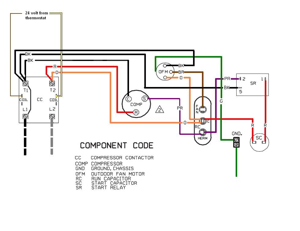
Let's dive into the often-overlooked, but critically important, wiring diagram for your condenser fan motor. Understanding this diagram isn't just for professional mechanics; it's a valuable tool for any experienced DIYer or modder looking to diagnose cooling issues, perform repairs, or even upgrade their cooling system. This guide will break down the diagram's components, symbols, and how to use it effectively.
Purpose of the Condenser Fan Motor Wiring Diagram
The wiring diagram acts as a roadmap for the electrical circuit that powers your condenser fan motor. It shows all the components involved – the motor itself, relays, fuses, sensors, and the wiring that connects them – and how they are interconnected. Understanding this diagram enables you to:
- Troubleshoot: Pinpoint the exact location of a fault in the electrical circuit when the condenser fan isn't working as expected.
- Repair: Replace damaged wiring or components with confidence, ensuring proper connections.
- Upgrade: Plan and execute modifications to your cooling system, like installing a more powerful fan or adding a manual override switch.
- Learn: Gain a deeper understanding of automotive electrical systems and how they function.
Key Specs and Main Parts
Before we jump into the diagram itself, let's define some crucial components and their relevant specifications. The specifics will vary from vehicle to vehicle, but the principles remain the same.
Main Parts:
- Condenser Fan Motor: The heart of the system. It’s an electric motor, typically a DC (Direct Current) motor, that spins the fan blades to draw air across the condenser. Specs to note:
- Voltage: Usually 12V DC in most passenger vehicles.
- Amperage (Current Draw): The amount of current the motor draws when operating. This is crucial for selecting appropriately sized fuses and relays. Look for this on the motor's label or in the vehicle's service manual.
- Horsepower (HP) / Wattage: Indicates the motor's power output, which affects the fan's airflow capacity.
- Relay(s): An electrically operated switch that controls the power flow to the fan motor. Using a relay allows a low-current signal from the engine control unit (ECU) or temperature sensor to switch on a high-current circuit powering the motor. Specs to note:
- Voltage Rating: Must be rated for at least 12V DC.
- Amperage Rating: Must be able to handle the motor's peak current draw. Choose a relay with a higher rating than the motor's expected draw for safety and longevity.
- Contact Configuration: Typically a Single Pole Single Throw (SPST) or Single Pole Double Throw (SPDT) relay.
- Fuse(s): A safety device that protects the circuit from overcurrent. It contains a thin wire that melts and breaks the circuit if the current exceeds a specified value. Specs to note:
- Amperage Rating: Should be slightly higher than the motor's normal operating current to allow for startup surges, but low enough to protect the wiring from overheating. Consult your vehicle's owner's manual or service manual for the correct fuse size.
- Type: Blade fuse, cartridge fuse, or fusible link are common types.
- Temperature Sensor/Switch: Monitors the temperature of the refrigerant or engine coolant and signals the ECU to activate the fan when a certain threshold is reached. In some simpler systems, the switch directly activates the relay.
- Engine Control Unit (ECU): The "brain" of the vehicle. It receives signals from various sensors, including the temperature sensor, and controls the activation of the condenser fan relay.
- Wiring: Conductors that connect all the components. Wire gauge (thickness) is critical. Undersized wiring can overheat and cause a fire. The diagram will usually specify the correct wire gauge for each section of the circuit.
Symbols: Decoding the Diagram
Understanding the symbols used in a wiring diagram is crucial for interpreting it correctly. Here are some common symbols you'll encounter:
- Lines: Represent wires. Solid lines typically indicate a direct connection, while dashed lines might indicate a shielded or grounded connection. Different line thicknesses might denote different wire gauges.
- Colors: Each wire is usually coded with a specific color (e.g., red for power, black for ground). Pay close attention to the color codes as they are standardized within a vehicle, even if not across all manufacturers.
- Resistors: Represented by a zigzag line. In this circuit, they might be part of the temperature sensor or used to provide a voltage drop.
- Capacitors: Shown as two parallel lines. Rarely found directly in a condenser fan motor circuit, but may be part of the ECU's internal circuitry controlling the fan.
- Ground: Typically depicted as three horizontal lines, decreasing in size from top to bottom. This indicates a connection to the vehicle's chassis, providing a return path for the current.
- Relay: Shown as a coil (the electromagnet) and a switch (the contacts). The diagram will show which terminals are the coil input, the common terminal, the normally open (NO) terminal, and the normally closed (NC) terminal.
- Fuse: Depicted as a wavy line inside a rectangle or a small, filled-in rectangle.
- Motor: Usually a circle with an "M" inside or a stylized representation of a motor.
- Connectors: Shown as interlocking shapes or circles. They indicate where wires connect and disconnect, allowing for component replacement.
A legend is your best friend! Most diagrams include a legend explaining all the symbols and color codes used. Always refer to the legend before attempting to interpret the diagram.
How It Works: Following the Current Flow
The basic operation is as follows:
- Power Source: The circuit starts with the vehicle's battery, which provides the 12V DC power.
- Ignition Switch (Sometimes): In some vehicles, the condenser fan motor circuit is only active when the ignition switch is in the "ON" or "ACC" position. This prevents the fan from running when the engine is off and draining the battery.
- Fuse: The power flows through a fuse, protecting the circuit from overcurrent.
- Temperature Sensor/Switch: When the refrigerant or coolant temperature reaches a predetermined threshold, the sensor sends a signal to the ECU (or directly closes the switch in simpler systems).
- ECU/Relay Activation: The ECU (or direct signal from the switch) energizes the relay coil.
- Relay Contacts Close: When the relay coil is energized, the relay contacts close, completing the circuit to the condenser fan motor.
- Motor Operation: The condenser fan motor receives power and starts spinning, drawing air across the condenser.
- Ground: The current returns to the battery through a ground connection.
Real-World Use: Basic Troubleshooting Tips
Here are some common problems and how the wiring diagram can help you diagnose them:
- Fan Doesn't Run at All:
- Check the fuse first! Use a multimeter to test for continuity across the fuse.
- Test the relay. You can usually swap it with a known working relay (e.g., from the horn) to see if that solves the problem. If you know how to use a multimeter, check for voltage at the relay coil when the engine is hot or the A/C is turned on. Also, check for continuity across the relay contacts when the coil is energized.
- Use the wiring diagram to trace the power flow. Check for voltage at the motor connector. If there's voltage but the motor doesn't run, the motor is likely faulty. If there's no voltage, trace back through the relay, fuse, and switch to find the break in the circuit.
- Inspect the wiring for damage, corrosion, or loose connections.
- Fan Runs Constantly:
- The temperature sensor/switch might be faulty and stuck in the "ON" position. Disconnect the sensor and see if the fan stops.
- The relay might be stuck in the closed position. Tap on the relay to see if it releases. If not, replace it.
- A short circuit in the wiring can also cause the fan to run constantly. Use the wiring diagram to identify potential short locations.
- Fan Runs Intermittently:
- Loose connections or corroded terminals are the most likely culprits. Inspect and clean all connections in the circuit.
- A failing relay can also cause intermittent operation.
Safety: Highlighting Risky Components
Working with automotive electrical systems involves certain risks. Always disconnect the negative battery cable before working on any electrical components to prevent accidental shorts and potential electrocution. Specifically, be cautious of the following:
- Battery: Contains corrosive acid and can produce explosive gases. Wear safety glasses and gloves when working near the battery.
- Wiring: Damaged or exposed wiring can cause shocks and fires. Always inspect wiring carefully before handling it.
- High-Current Circuits: The condenser fan motor circuit can draw significant current. Shorts in this circuit can cause overheating and fires. Always use appropriately sized fuses and wiring.
Never work on electrical components when the engine is running.
We have a sample condenser fan motor wiring diagram file that you can download for further study. It can be an invaluable reference tool as you delve deeper into understanding and troubleshooting these circuits. Remember to always consult your vehicle's specific service manual for the most accurate and detailed information.