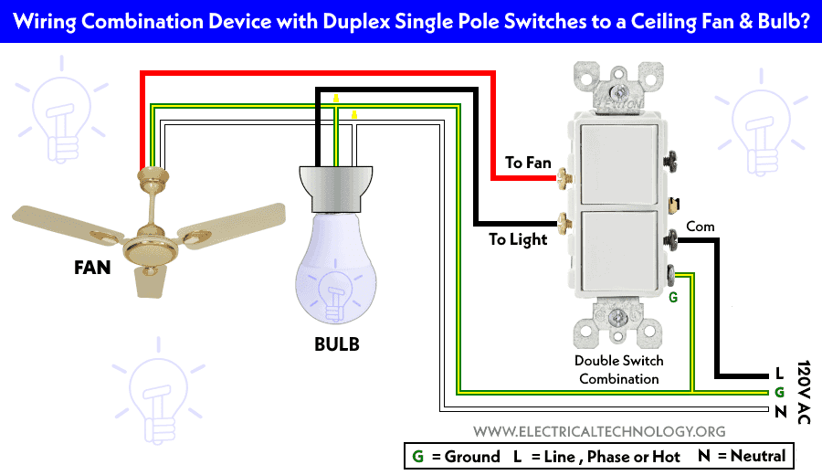
Wiring Diagram For Double Switch For Fan And Light
Alright, let's dive into wiring a double switch for a fan and light. This is a common mod in vehicles, especially for interior upgrades, RVs, or even custom lighting setups. Understanding this wiring diagram isn't just about fixing something that's broken; it's about empowering you to customize your ride and grasp fundamental electrical principles. Whether you're adding a cooling fan to your amplifier rack, installing accent lights, or just want independent control of a dome light and its auxiliary reading lamp, this knowledge is invaluable.
Purpose
Why bother learning this? Here are a few scenarios:
- Repairing existing circuits: Maybe your fan or light switch has failed, and you need to troubleshoot the wiring. This diagram provides a roadmap.
- Upgrading: Want to add a separate switch for a fan that previously ran off the same circuit as the light? This shows you how to do it independently.
- Customization: Building a custom panel with independent control of various accessories? This is your foundation.
- Learning: Understanding basic electrical circuits is essential for any DIY mechanic. This is a practical example to build upon.
Key Specs and Main Parts
Before we get into the diagram, let's identify the key components and specs involved. These will vary depending on your application, but here are the basics:
- Double Switch: This is the heart of the system. A double switch, sometimes called a dual or combination switch, allows you to control two separate circuits (fan and light) from a single housing. They typically have six terminals: one common input for power and two outputs for each switch (on/off). Make sure the switch's amperage rating exceeds the combined load of your fan and light.
- Power Source (12V DC): Most automotive applications use a 12V DC (Direct Current) system. This can be the vehicle's battery, a dedicated accessory power distribution block, or a fused circuit from the main fuse box.
- Fuse(s): Crucially important! A fuse protects the circuit from overloads and short circuits. Choose a fuse with an amperage rating slightly higher than the expected draw of the fan *or* the light, depending on whether they are fed by separate fuses. If they share a single fuse it will need to be slightly higher than the combined draw of both. Always consult your fan and light specifications for their current draw.
- Wiring: Choose automotive-grade wire of the appropriate gauge (thickness) for the current draw. Thicker wire is required for higher amperage loads. Use a wire gauge chart to determine the appropriate size. 16 or 18 gauge is commonly used for interior lighting and low-power fans, but always verify.
- Fan: Specify its voltage (typically 12V DC) and current draw (in Amps).
- Light: Specify its voltage (typically 12V DC) and power consumption (in Watts). Convert Watts to Amps using the formula: Amps = Watts / Volts. This is important for selecting the correct fuse and wire gauge.
- Connectors: Crimp connectors, butt connectors, spade connectors, or solder. Choose quality connectors and tools to ensure secure and reliable connections.
Symbols – Understanding the Diagram
Wiring diagrams use a standard set of symbols to represent components. Here's a breakdown of the symbols you'll encounter in our double switch diagram:
- Solid Lines: Represent wires. The thickness of the line doesn't necessarily indicate wire gauge in most simplified diagrams.
- Dashed Lines: Might represent a wire that is grounded or shielded, or perhaps a connection on the back of the switch that isn't normally visible.
- Circles: Can represent various components, depending on what's inside the circle. Usually a fuse or relay coil.
- Rectangles: Often represent switches, relays, or other control devices.
- Ground Symbol (Typically three horizontal lines decreasing in size): Indicates a connection to the vehicle's chassis or the negative terminal of the battery. This provides a return path for the current.
- Battery Symbol (+/-): Represents the power source, indicating positive (+) and negative (-) terminals.
- Switch Symbol: A line with a pivot point. In a double switch, you'll see two of these within the rectangle representing the switch body.
- Fan Symbol: Varies, but often represented as a stylized fan blade within a circle.
- Light Symbol: Varies, but often represented as a circle with an "X" inside.
Wire Colors: While not universally standardized, some colors are commonly used:
- Red: Typically indicates a positive (+) power wire.
- Black: Typically indicates a ground (-) wire.
- Other Colors (e.g., Blue, Yellow, Green): Used for switched outputs or other signal wires. Keep a consistent color scheme in your modifications for future troubleshooting.
How It Works
Here's the basic flow of electricity in a double switch setup for a fan and light:
- Power Input: A 12V DC power source is connected to the common input terminal on the double switch. This is usually a red wire connected to the positive (+) terminal of the battery or a fused accessory circuit.
- Switching Action: When you flip the first switch, it connects the common input terminal to one of its output terminals. This completes the circuit to the fan.
- Fan Activation: The current flows from the switch, through the wiring, to the fan, providing power to the fan motor. The fan then draws the electricity it needs and returns the current to the negative (-) terminal of the battery through the vehicle's chassis ground or a dedicated ground wire.
- Light Control: Similarly, when you flip the second switch, it connects the common input terminal to its other output terminal, completing the circuit to the light.
- Light Illumination: The current flows from the switch to the light, illuminating it. Like the fan, the light circuit returns the current to the battery's negative terminal via ground.
- Independent Control: Because each switch controls its own output, you can turn the fan and light on or off independently.
Real-World Use – Basic Troubleshooting Tips
Here are some common problems and how to troubleshoot them:
- Neither the fan nor the light works: Check the main fuse. Also, verify that the power source is active (e.g., the ignition switch is in the "on" position if using an accessory circuit). Use a multimeter to check for voltage at the common input terminal of the double switch.
- One of the devices works, but the other doesn't: Check the fuse specifically for the non-working device (if separate fuses are used). Use a multimeter to test for continuity through the switch when it is in the "on" position. Test the ground connection for the faulty device.
- The fuse blows repeatedly: Indicates a short circuit. Inspect the wiring for damage or exposed wires that may be contacting the vehicle's chassis. Disconnect the fan or light (whichever is associated with the blown fuse) and try replacing the fuse. If the fuse still blows, the short is in the wiring between the switch and the device. If the fuse doesn't blow, the short is in the fan or light itself.
- The fan or light is dim/weak: Could indicate a poor ground connection, undersized wiring, or a low battery voltage.
Safety – Handling Risky Components
Working with automotive electrical systems can be dangerous if proper precautions aren't taken. Here are some safety considerations:
- Disconnect the Battery: Always disconnect the negative (-) terminal of the battery before working on any electrical wiring. This prevents accidental short circuits and potential electric shock.
- Identify Live Wires: Use a multimeter or circuit tester to identify live wires before cutting or splicing them.
- Use Proper Tools: Use crimping tools and insulated wire strippers designed for automotive wiring. Don't use household tools.
- Protect Exposed Wires: Use heat shrink tubing or electrical tape to insulate all exposed wire connections.
- Fuses are Crucial: Never bypass a fuse or use a fuse with a higher amperage rating than specified. This could lead to a fire.
- Beware of Airbags: If working near airbags, consult your vehicle's service manual for proper deactivation procedures. Accidental airbag deployment can cause serious injury.
- High Amp Circuits: Circuits with very high amperage draws (over 20 amps) can generate significant heat. Be extra careful with wire gauge and connector selection in these circuits. Consider using a relay to switch the load, reducing the current flowing through the switch itself.
With a good understanding of the wiring diagram and safe practices, you can confidently tackle this mod and enjoy the benefits of customized control over your vehicle's accessories. We have a detailed, downloadable wiring diagram available to guide you through the process. Contact us, and we'll provide you with the file.