Wiring Diagram For Electric Brakes On A Trailer
For intermediate car owners, modders, or DIY mechanics tackling trailer electrical projects, understanding electric brake wiring is paramount. This article provides a detailed, yet approachable, explanation of trailer electric brake wiring diagrams. We'll break down the components, wiring, symbols, and troubleshooting so you can confidently maintain, repair, or upgrade your trailer's braking system.
Purpose: Why Understanding Electric Brake Wiring Matters
A solid understanding of electric brake wiring diagrams is invaluable for several reasons:
- Repair & Maintenance: Quickly diagnose and fix brake malfunctions, like intermittent braking or complete failure. This saves time and money compared to relying solely on professional mechanics.
- Upgrades & Modifications: Safely install new brake controllers, add auxiliary power circuits, or upgrade your trailer's wiring.
- Safety & Compliance: Ensure your trailer's braking system meets legal requirements and functions reliably, preventing accidents.
- Learning & Skill Development: Expand your automotive knowledge and gain confidence in tackling more complex electrical projects.
Key Specs and Main Parts
Before diving into the diagram itself, let's define the core components and their specifications. These are the building blocks of the electric brake system.
- Brake Controller: Located in the tow vehicle, the brake controller sends an electrical signal to the trailer's brakes, proportional to the tow vehicle's deceleration. Many modern controllers are proportional, meaning they apply more braking power based on the rate of deceleration (detected by an internal accelerometer), providing smoother and safer stops. Older controllers are often time-delayed, applying a preset voltage after a short delay. The controller typically requires a 12V power source, a ground connection, a connection to the brake light switch signal, and an output wire to the trailer connector.
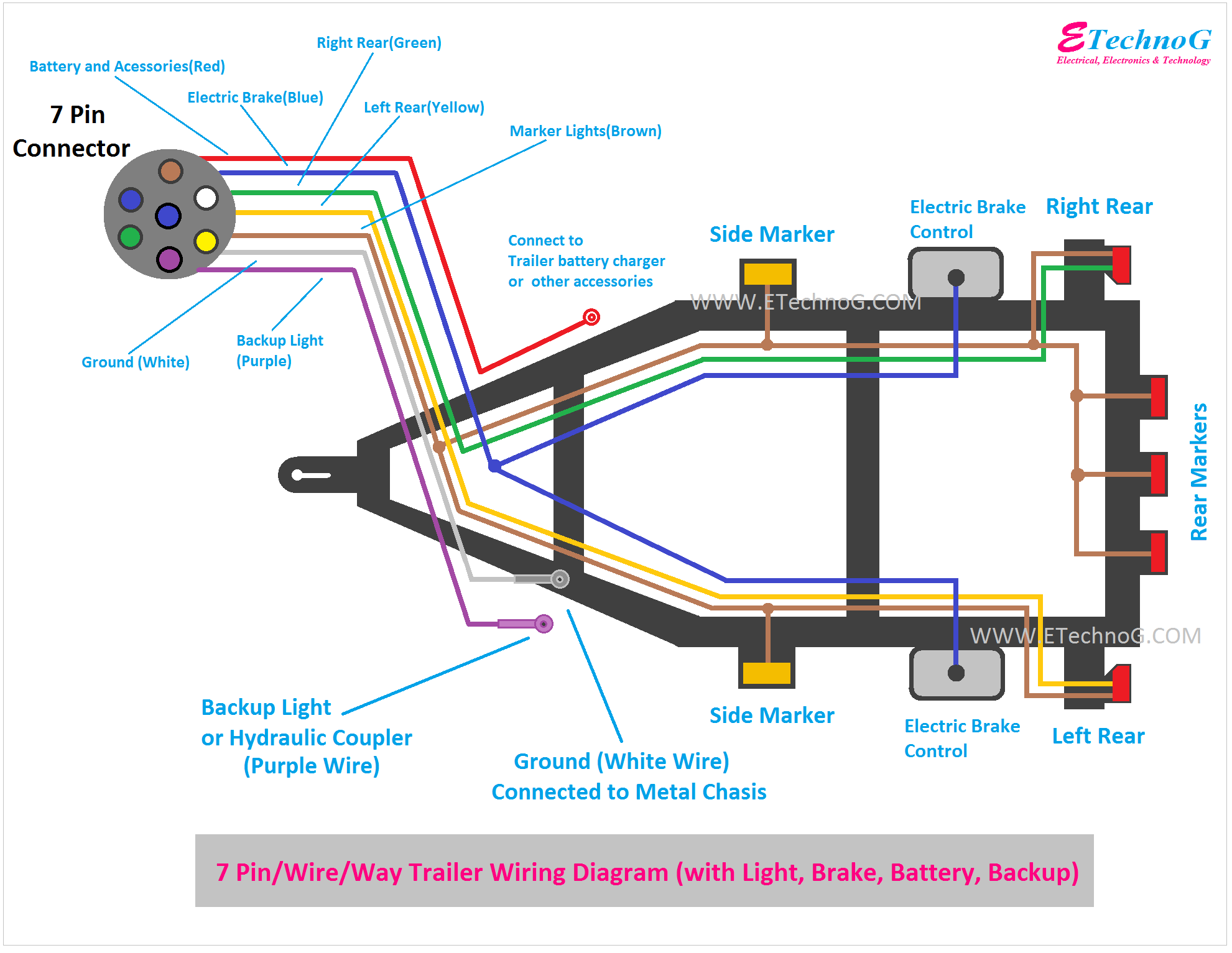
- Trailer Connector (Typically 7-Way): The interface between the tow vehicle and the trailer, carrying signals for brakes, lights (running, turn, brake), and often a 12V auxiliary power feed. The 7-way connector is the most common type for trailers with electric brakes. Its pins follow a standard configuration.
- Wiring Harness: The network of wires connecting all the components. Quality, appropriately sized wiring is crucial for reliable performance and safety. Gauge refers to the wire's diameter; a lower gauge number indicates a thicker wire. For electric brakes, 12- or 10-gauge wire is generally recommended for the brake output circuit to handle the current draw.
- Electric Brake Assemblies: Located within each wheel hub, the electric brake assembly converts electrical energy into mechanical braking force. It consists of an electromagnet, brake shoes, a drum, and associated hardware. When energized, the electromagnet attracts the armature on the drum, creating friction that applies the brakes.
- Breakaway Switch: A crucial safety device. If the trailer becomes detached from the tow vehicle, the breakaway switch activates the trailer brakes, bringing it to a stop. It works by pulling a pin connected to a cable, which completes a circuit, energizing the trailer brakes via a dedicated battery.
- Trailer Battery (Optional, but Recommended): Used to power the breakaway switch and can also supply power for interior lights or other trailer accessories. Even if your trailer lights are getting power from the tow vehicle, a trailer battery is vital for the breakaway system to function in an emergency.
Decoding the Wiring Diagram: Symbols and Conventions
A wiring diagram is a schematic representation of the electrical circuits. Understanding the symbols and conventions is essential for interpreting the diagram correctly.
- Lines: Represent wires. Solid lines indicate a continuous connection, while dashed lines may indicate a connection running along the trailer frame or a less critical connection.
- Colors: Wires are typically color-coded to aid in identification. Common color codes include:
- Blue: Electric brake output
- White: Ground
- Brown: Right turn/brake light
- Green: Left turn/brake light
- Yellow: Tail/running lights
- Red: Auxiliary power (often for breakaway switch or interior lights)
- Black: 12V power supply
- Symbols: Standardized symbols represent components:
- Resistor: A zig-zag line
- Capacitor: Two parallel lines
- Ground: Three horizontal lines, decreasing in length
- Switch: A break in a line, with a pivoting arm indicating the switch state.
- Brake Magnet: Often a coil symbol with lines indicating magnetic field.
- Connector: Circles or squares linked by lines.
- Numbering/Labeling: Wires are often labeled with numbers or letters to indicate their function and destination. This is particularly helpful when tracing circuits.
How It Works: The Electric Brake Circuit in Action
The electric brake circuit is a relatively simple system, but understanding its operation is crucial for troubleshooting. Here's a breakdown of the signal flow:
- The driver applies the brakes in the tow vehicle.
- The brake controller senses the deceleration and sends a variable voltage signal (0-12V DC) to the blue wire in the trailer connector.
- The blue wire carries the signal to the trailer's electric brake assemblies.
- Within each brake assembly, the voltage energizes the electromagnet.
- The electromagnet attracts the armature on the brake drum, creating friction and applying the brakes. The amount of braking force is proportional to the voltage applied by the brake controller.
- The breakaway switch, connected to a dedicated battery, provides a fail-safe. If the trailer separates, the switch activates, sending 12V directly to the brake magnets, bringing the trailer to a stop.
Real-World Use: Basic Troubleshooting Tips
Here are some common electric brake problems and how to troubleshoot them, using the wiring diagram as a guide:
- No Brakes:
- Check the brake controller settings and connections in the tow vehicle.
- Verify the trailer connector is securely plugged in and the pins are clean and undamaged.
- Inspect the blue wire for breaks or shorts. Use a multimeter to check for voltage at the brake magnets when the brakes are applied.
- Test the breakaway switch and battery. Ensure the battery is charged and the switch is functioning correctly.
- Weak or Intermittent Brakes:
- Check the wiring for loose connections or corrosion, especially at the trailer connector and brake magnets.
- Inspect the brake magnets for wear or damage. Test their resistance with a multimeter; abnormally high or low resistance indicates a problem.
- Ensure the brake controller is properly calibrated and functioning correctly.
- Brakes Locking Up:
- Check the brake controller settings. The gain may be set too high.
- Inspect the brake magnets for excessive wear or damage. Sometimes magnets can become overly aggressive.
Safety Considerations
Working with electrical systems involves inherent risks. Follow these safety precautions:
- Disconnect Power: Always disconnect the trailer from the tow vehicle and disconnect the trailer battery before working on the wiring.
- Use Proper Tools: Use insulated tools and a multimeter to avoid electrical shock and damage to components.
- Inspect Wiring: Thoroughly inspect wiring for damage, wear, or corrosion. Replace damaged wiring immediately.
- Work in a Dry Environment: Avoid working on electrical systems in wet or damp conditions.
- Be Aware of Capacitors: Some brake controllers may contain capacitors that can store a charge even after power is disconnected. Discharge capacitors before handling them.
- Fuses: Properly sized fuses are critical for protecting the system from overloads and short circuits. Always replace blown fuses with the correct amperage rating.
By understanding the information contained within the electric brake wiring diagram and practicing safe work habits, you can confidently tackle trailer brake repairs and upgrades, ensuring the safety of yourself and others on the road. Download the detailed wiring diagram for electric brakes to get started.
We have the file, and you can download the diagram.