
Wiring Diagram For Electric Fan Relay
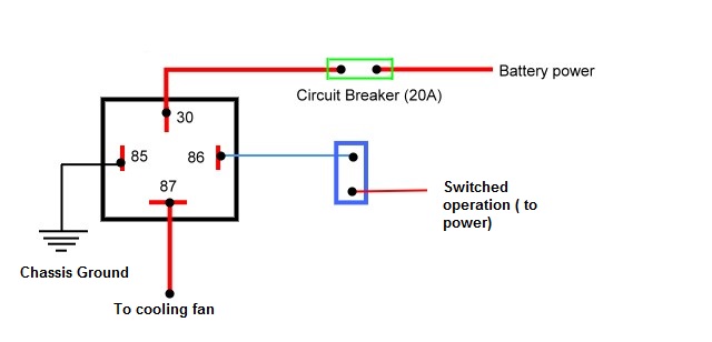
Let's dive into a crucial component for keeping your engine cool: the electric fan relay circuit. Whether you're troubleshooting a malfunctioning fan, upgrading your cooling system for better performance, or simply expanding your automotive knowledge, understanding this circuit is invaluable. This article will break down the wiring diagram, explain its function, and give you the practical knowledge you need to work on it safely and effectively.
Purpose of Understanding the Electric Fan Relay Wiring Diagram
Why bother learning about this specific circuit? The electric fan relay circuit plays a vital role in maintaining your engine's optimal operating temperature. Here's why understanding its wiring diagram is important:
- Troubleshooting: A malfunctioning electric fan can lead to overheating, causing serious engine damage. A clear wiring diagram allows you to systematically trace the circuit, identify faulty components (like a bad relay, sensor, or wiring), and repair them.
- Upgrades and Modifications: Installing a higher-flow electric fan, adding a secondary fan, or creating a custom fan control system all require a solid understanding of the existing wiring and how to integrate new components.
- Performance Enhancement: You might want to modify the fan's operation to cool the engine more efficiently, especially in performance applications. A diagram is crucial for safely making these changes.
- Learning and Education: Understanding the electric fan relay circuit is a great stepping stone for learning more about automotive electrical systems in general. It's a relatively simple circuit that illustrates fundamental concepts.
Key Specs and Main Parts of the Electric Fan Relay Circuit
Before we look at the wiring diagram itself, let's identify the key components and their general specifications. Keep in mind that specific values (voltage, amperage, resistance) will vary depending on your vehicle and the specific fan system.
- Battery: The power source for the entire circuit. Typically a 12V DC system.
- Fuse: A safety device designed to protect the circuit from overcurrent. Often located in the fuse box. Fuses are rated in Amperes (A) and should be replaced with the same amperage rating.
- Ignition Switch: Provides a switched power source. Often used to enable the fan under certain conditions (e.g., when the engine is running).
- Temperature Sensor (Coolant Temperature Sensor - CTS): Monitors the engine coolant temperature. The sensor's resistance changes with temperature, providing a signal to the Engine Control Unit (ECU) or a dedicated fan control module. Some older systems used a temperature switch that directly closed a circuit at a specific temperature.
- Engine Control Unit (ECU) or Fan Control Module: Receives the temperature signal and decides when to activate the fan. In older cars, this function may be handled by a simple thermal switch.
- Relay: An electromagnetic switch that allows a low-current circuit (from the ECU) to control a high-current circuit (powering the fan).
- Electric Fan: The actual cooling device. Requires a substantial amount of current to operate.
- Wiring: Connects all the components. Wire gauge (thickness) is important to handle the current flow without overheating. Thicker wires are needed for the high-current fan motor circuit.
- Ground Connection: Provides a return path for the current. A good, clean ground is essential for proper operation.
Understanding Wiring Diagram Symbols
Wiring diagrams use standardized symbols to represent components and connections. Here's a breakdown of common symbols you'll encounter in an electric fan relay diagram:
- Lines: Represent wires. Solid lines indicate a direct connection. Dashed lines might indicate a connection through a connector or a shielded cable.
- Colors: Wires are often color-coded. This helps with identification and troubleshooting. Common colors include Red (power), Black (ground), Blue, Green, Yellow, and White. Always refer to the specific wiring diagram for your vehicle's color codes, as they can vary.
- Battery Symbol: A series of long and short parallel lines. The longer line represents the positive (+) terminal.
- Fuse Symbol: A squiggly line or a rectangle with a line through it.
- Relay Symbol: A coil (representing the relay's electromagnet) and a switch (representing the contacts that open and close to control the fan).
- Ground Symbol: A series of horizontal lines decreasing in size.
- Resistor Symbol: A zigzag line. (Relevant if the temperature sensor is a thermistor, a type of resistor whose resistance changes with temperature).
- Motor Symbol: A circle with an "M" inside.
- Switch Symbol: A line that can be either connected or disconnected from another line.
Important Note: Some diagrams will also include numbers or letters next to the wires. These refer to specific pin numbers on connectors or internal designations within the ECU. These identifiers are vital for accurate diagnosis and repair.
How the Electric Fan Relay Circuit Works
Let's trace the flow of electricity through the circuit:
- Power Source: The battery provides the initial power. This power is typically routed through a fuse to protect the circuit.
- Ignition Interlock (Optional): In some systems, the ignition switch must be in the "on" position for the fan to operate. This prevents the fan from draining the battery when the engine is off.
- Temperature Sensing: The coolant temperature sensor (CTS) monitors the engine's coolant temperature.
- ECU/Fan Control Module Decision: The CTS sends a signal to the ECU or a dedicated fan control module. The ECU compares the temperature reading to a pre-programmed threshold.
- Relay Activation: If the coolant temperature exceeds the threshold, the ECU sends a low-current signal to the relay coil. This energizes the electromagnet inside the relay.
- Switch Closure: The energized electromagnet pulls a switch inside the relay, connecting the high-current circuit.
- Fan Power: Power from the battery (again, typically through a fuse) flows through the closed relay contacts to the electric fan motor.
- Fan Operation: The fan motor spins, drawing air through the radiator to cool the engine.
- Ground Path: The current returns to the battery through a ground connection.
Think of the relay as a "remote control" for the fan. The ECU doesn't directly power the fan because the fan requires too much current. Instead, the ECU controls the relay, which then switches the high-current power to the fan.
Real-World Use and Basic Troubleshooting
Here are some common problems you might encounter and how to troubleshoot them using the wiring diagram:
- Fan Not Working At All:
- Check the fuse(s). A blown fuse is a common cause.
- Test the relay. You can often swap it with another identical relay in the fuse box to see if that fixes the problem. You can also use a multimeter to check for continuity across the relay's contacts when it's energized.
- Check the fan motor itself. Use a multimeter to check for voltage at the fan motor connector when the engine is hot enough to trigger the fan. If voltage is present but the fan doesn't spin, the motor is likely bad.
- Inspect the wiring for damage or loose connections. Pay close attention to the ground connection.
- Fan Always Running:
- Check the temperature sensor. A faulty sensor can send an incorrect signal to the ECU.
- Check the relay. The relay might be stuck in the "on" position.
- Check the wiring for a short to ground in the control circuit of the relay.
- Intermittent Fan Operation:
- This is often caused by a loose connection or a failing component. Carefully inspect all wiring and connectors.
- Monitor the coolant temperature and fan operation to see if there's a correlation.
Safety Precautions
Working with automotive electrical systems can be dangerous. Always take the following precautions:
- Disconnect the battery: Before working on any electrical component, disconnect the negative (-) terminal of the battery to prevent accidental shorts.
- Work in a well-lit area: Good visibility is essential for identifying components and wiring.
- Use appropriate tools: Use insulated tools designed for automotive electrical work.
- Be careful with the relay: The relay carries a significant amount of current. Avoid touching the terminals when the circuit is energized.
- Never bypass a fuse: If a fuse blows repeatedly, there's a problem in the circuit. Find and fix the underlying cause, don't just replace the fuse with a higher amperage rating. This can cause a fire.
High-current circuits, especially those powering the fan motor, can generate significant heat if there's a fault. Be cautious when inspecting these circuits.
By understanding the wiring diagram and the function of each component, you can effectively troubleshoot and repair electric fan relay circuits, saving yourself time and money while keeping your engine running cool. Remember to always consult the specific wiring diagram for your vehicle model for accurate information.
We have an example wiring diagram file that will help you understand all of this article. Please feel free to ask if you want to download this file.