
Wiring Diagram For Electric Radiator Fan
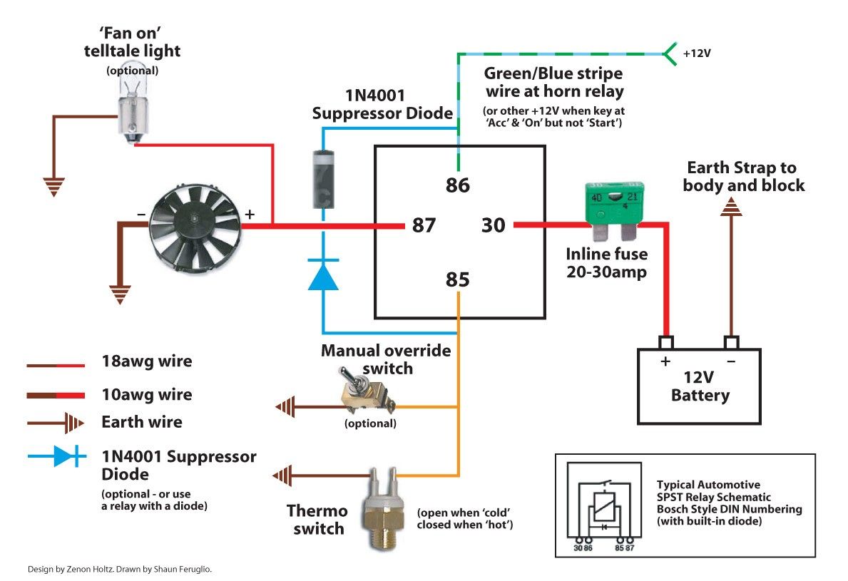
Alright, let's dive into wiring diagrams for electric radiator fans. This is a critical system for maintaining your engine's temperature, and understanding how it's wired is essential for repairs, upgrades (like converting to electric from a belt-driven fan), and even diagnosing general cooling issues. Having a solid grasp of the wiring gives you the power to troubleshoot problems yourself, saving time and money. Plus, when modifying your car, knowing the ins and outs prevents accidental short circuits and fried components. We've got a downloadable diagram available too, which we'll mention at the end, making this process even easier.
Why This Diagram Matters
Think of a wiring diagram as the blueprint for your electric fan system. It visually represents every connection, component, and wire involved. Without it, you're essentially guessing when trying to diagnose a faulty fan, install a new controller, or perform any modifications. This knowledge is especially valuable for:
- Troubleshooting: Identifying breaks in the circuit, short circuits, or faulty components.
- Repairs: Knowing where to disconnect and reconnect wires during component replacement.
- Upgrades: Adding features like adjustable fan speed controllers or temperature gauges.
- Conversions: Switching from a mechanical fan to an electric fan setup.
- Learning: Simply understanding how the system is designed and functions.
Key Specs and Main Parts
Before we dissect a diagram, let's identify the key players in an electric radiator fan system:
- Electric Fan Motor: This is the heart of the system, drawing power to spin the fan blades and draw air through the radiator. Fan motors come in various sizes and power ratings, typically operating at 12V DC. Amperage draw is a crucial spec here; too high, and you risk overloading your circuit.
- Temperature Sensor/Switch: This device monitors the coolant temperature. When the temperature reaches a preset threshold (e.g., 200°F), the switch closes, completing the circuit and turning on the fan. These can be simple on/off switches or more sophisticated sensors feeding data to an ECU.
- Relay: An electromagnetic switch that uses a small current to control a larger current. The temperature switch triggers the relay, which then provides power to the fan motor. Relays are essential because the temperature switch usually can't handle the high amperage of the fan motor directly. A standard automotive relay often has terminals labeled 30, 85, 86, and 87 (or 87a for a normally closed connection).
- Fuse: A safety device designed to protect the circuit from overcurrent. If the current exceeds the fuse's rating (e.g., 30 amps), the fuse blows, breaking the circuit and preventing damage to other components. The fuse rating should be slightly higher than the fan motor's maximum amperage draw.
- Wiring: The network of wires that connects all the components. The gauge (thickness) of the wire is critical. Using too thin a wire can lead to overheating and voltage drop, reducing fan performance and potentially causing a fire. Always use automotive-grade wire rated for the expected current and temperature.
- ECU (Engine Control Unit): In many modern vehicles, the electric fan is controlled by the ECU. The ECU receives temperature data from a coolant temperature sensor and controls the fan relay based on programmed parameters.
Decoding the Symbols
Wiring diagrams use standardized symbols to represent different components. Here's a breakdown of common symbols you'll encounter:
- Straight Lines: Represent wires. A thicker line often indicates a thicker wire (higher gauge). Dashed lines might indicate shielded wiring or a ground connection.
- Circles with a Cross: Typically represent light bulbs or indicator lights. In our case, it might be a visual indicator for the fan operation.
- Rectangles: Can represent a variety of components, including relays, switches, and control modules. Specific labels inside the rectangle identify the component.
- Coil Symbol: Represents a relay coil.
- Ground Symbol (typically three horizontal lines decreasing in length): Indicates a connection to the vehicle's chassis ground (negative terminal of the battery).
- Fuse Symbol (zigzag line inside a rectangle): Represents a fuse.
- Color Codes: Wires are often color-coded to help identify them. Common colors include red (power), black (ground), blue, green, yellow, and white. The diagram will usually include a legend that explains the color codes.
Example Color Codes:
B = Black, R = Red, W = White, G = Green, Y = Yellow, Br = Brown, Lb = Light Blue
How It Works: A Typical Circuit
Let's trace the flow of electricity in a typical electric radiator fan circuit. Imagine we're using a temperature switch and a relay:
- Power Source: Power is supplied from the vehicle's battery through a fused connection. This is typically a 12V DC source.
- Relay Activation: The fused power wire connects to terminal 30 on the relay. A separate wire runs from the temperature switch to terminal 86 on the relay coil. Terminal 85 of the relay coil is connected to ground.
- Temperature Threshold: When the coolant temperature reaches the set point of the temperature switch, the switch closes, completing the circuit to ground. This energizes the relay coil.
- Relay Operation: When the relay coil is energized, it pulls the internal contacts together, connecting terminal 30 to terminal 87.
- Fan Power: A heavy-gauge wire runs from terminal 87 on the relay to the positive (+) terminal of the electric fan motor. The negative (-) terminal of the fan motor is connected to ground.
- Fan Activation: With the relay closed, power flows from the battery, through the fuse, to the relay, to the fan motor, and finally to ground, causing the fan to spin.
- Cooling and Deactivation: As the fan draws air through the radiator, the coolant temperature drops. Once the temperature falls below the switch's set point, the switch opens, de-energizing the relay coil, and the fan shuts off.
Real-World Use: Basic Troubleshooting
Okay, so the fan isn't working. What do you do? Here are some basic troubleshooting steps, assuming you have your wiring diagram handy:
- Check the Fuse: This is the first and easiest step. Use a multimeter to verify continuity across the fuse. If it's blown, replace it with a fuse of the same amperage rating.
- Test the Relay: You can test the relay using a multimeter to check for continuity between terminals 30 and 87 when the relay coil is energized (apply 12V to terminals 85 and 86). You can also swap the relay with a known good relay of the same type to see if that resolves the issue.
- Verify Power and Ground: Use a multimeter to check for 12V at the positive (+) terminal of the fan motor and a good ground connection at the negative (-) terminal.
- Test the Temperature Switch: With the engine running and warmed up, use a multimeter to check for continuity across the temperature switch terminals. If there's no continuity when the engine is hot, the switch is likely faulty.
- Inspect Wiring: Visually inspect all wiring for any signs of damage, corrosion, or loose connections. Use a wire brush to clean corroded connections.
Safety First
Working with electrical systems involves inherent risks. Here are some safety precautions:
- Disconnect the Battery: Always disconnect the negative (-) terminal of the battery before working on any electrical components. This prevents accidental short circuits.
- Handle Fuses with Care: Avoid touching exposed metal parts of fuses when the circuit is energized.
- Use Proper Tools: Use insulated tools designed for automotive electrical work.
- Work in a Well-Ventilated Area: When soldering, work in a well-ventilated area to avoid inhaling fumes.
- Never Bypass a Fuse: Bypassing a fuse can lead to overheating and a potential fire. Always replace a blown fuse with one of the correct amperage rating.
- The ECU is especially sensitive to voltage spikes; be extremely careful when probing near it.
Electric radiator fan systems are relatively straightforward, but understanding the wiring diagram is crucial for effective troubleshooting and modifications. Take your time, double-check your connections, and always prioritize safety. We have a downloadable wiring diagram available, which should help tremendously with your project. Knowing how electricity flows through the car's cooling system is a valuable skill that will save you both time and money.
(Note: Because we cannot provide a true file download here, imagine a button here that says "Download Electric Radiator Fan Wiring Diagram" which, when clicked, would provide the reader with the diagram file.)