
Wiring Diagram For Ford Starter Solenoid
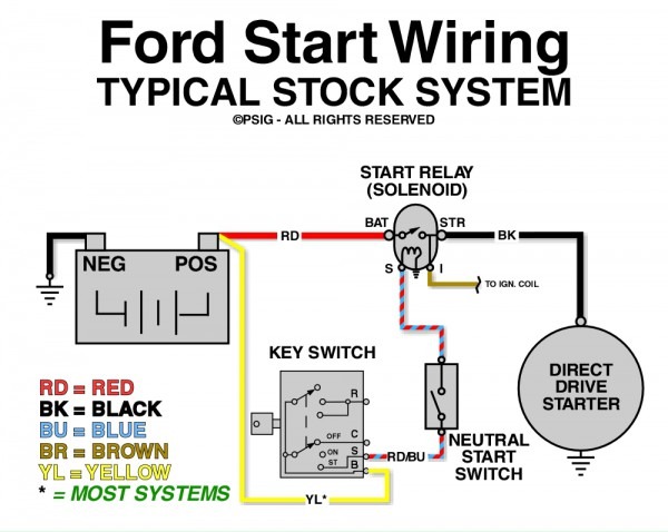
Alright, let's dive into the wiring diagram for a Ford starter solenoid. Whether you're wrestling with a no-start condition, upgrading your electrical system, or just want a deeper understanding of how your vintage Ford cranks to life, understanding this circuit is crucial. We're going to break down the key components, decipher the diagram symbols, and equip you with the knowledge to diagnose and fix common starter solenoid issues.
Purpose of Understanding the Ford Starter Solenoid Wiring Diagram
Why bother learning this stuff? Simple: the starter system is the gateway to your engine's operation. A faulty starter solenoid can leave you stranded, and blind troubleshooting can lead to further damage or wasted money. A proper wiring diagram allows you to:
- Accurately diagnose starting problems.
- Safely repair or replace faulty components.
- Understand the flow of electricity within the starting circuit.
- Customize or upgrade your electrical system (e.g., adding remote start).
- Verify proper installation of new parts.
Key Specs and Main Parts of the Ford Starter System
Before we get into the diagram itself, let's review the essential players:
- Battery: The heart of the electrical system, providing the initial voltage (typically 12V) required to power the starter.
- Ignition Switch: The control center. Turning the key sends a signal to the starter solenoid.
- Starter Solenoid: An electromagnetic switch. When activated by the ignition switch, it closes a high-current circuit between the battery and the starter motor. On older Fords, this solenoid is usually mounted on the inner fender well, away from the starter itself. Newer vehicles often integrate the solenoid directly into the starter motor.
- Starter Motor: A powerful electric motor that turns the engine's flywheel (or flexplate) to initiate the combustion process.
- Ground Connections: Critical for completing the circuit. A poor ground can cause all sorts of intermittent issues.
- Wiring and Fuses: The pathways and protective devices that carry electrical current.
It’s important to note that Ford used different solenoid configurations over the years. The most common are the 4-post and 3-post solenoids. The diagram you'll download (more on that later) covers both, clearly illustrating the differences.
Decoding the Wiring Diagram: Symbols, Lines, and Colors
Wiring diagrams can seem intimidating at first, but once you understand the symbols, they become much easier to interpret. Here’s a breakdown:
- Lines: Represent wires. Thicker lines often indicate wires carrying higher current (e.g., the battery cable to the solenoid).
- Colors: Wires are typically color-coded. The diagram will include a color key indicating what each color represents (e.g., Red = Battery +, Black = Ground, Yellow = Starter Signal). Always verify the wire colors on your specific vehicle, as slight variations can occur.
- Battery Symbol: Usually represented by a series of short and long parallel lines. The positive terminal is often marked with a "+" sign.
- Ignition Switch Symbol: Represented as a switch that opens and closes the circuit.
- Solenoid Symbol: A coil symbol represents the solenoid's electromagnet, with terminals for the control signal and the high-current connections.
- Starter Motor Symbol: A circle with an "M" inside.
- Ground Symbol: Often shown as a series of downward-facing lines, indicating a connection to the vehicle's chassis.
- Fuse Symbol: A zigzag line inside a rectangle, indicating a circuit protection device.
Also, expect to see numbers and letters near the terminals. These indicate the specific pin or connection point on the component. For example, you might see "S" for the starter signal terminal on the solenoid.
How the Ford Starter Solenoid Circuit Works
Here's the sequence of events when you turn the key:
- When you turn the ignition key to the "Start" position, voltage is sent from the ignition switch to the small terminal (usually marked "S") on the starter solenoid.
- This voltage energizes the solenoid's electromagnetic coil.
- The energized coil pulls a plunger, closing a heavy-duty switch inside the solenoid.
- Closing this switch connects the battery's positive terminal (through a thick cable) directly to the starter motor.
- The starter motor spins, engaging the pinion gear with the flywheel, and turning the engine.
- When you release the key, the voltage to the solenoid is cut off, the coil de-energizes, and the plunger returns to its original position, disconnecting the starter motor from the battery.
In a 4-post solenoid, the fourth post is often used to bypass the ballast resistor (or resistor wire) during starting, providing full battery voltage to the ignition coil for a stronger spark. This is important on older vehicles with points-type ignition systems.
Real-World Use: Basic Troubleshooting Tips
Here are some common symptoms and troubleshooting steps:
- Clicking Sound, No Start: This could indicate a low battery, corroded connections, a faulty solenoid, or a bad starter motor. Start by checking the battery voltage and cleaning the battery terminals. Then, check the solenoid connections. You can try jumping the two large terminals on the solenoid (with the ignition off and the transmission in Park or Neutral!) to see if the starter engages. Be extremely careful when doing this, as it bypasses the ignition switch and can be dangerous!
- No Sound, No Start: Check the ignition switch and the wiring to the solenoid's "S" terminal. Use a multimeter to verify that voltage is reaching the solenoid when the key is in the "Start" position. Also, check the ground connections.
- Starter Stays Engaged: This is often caused by a faulty solenoid that's sticking in the engaged position. Replace the solenoid immediately.
- Slow Cranking: Could be due to a weak battery, corroded connections, or a failing starter motor. Perform a voltage drop test on the starter circuit to pinpoint the issue.
Safety First: Highlighting Risky Components
Working on the starter system involves dealing with high currents and potential hazards:
- Battery: Always disconnect the negative battery cable before working on the electrical system. This prevents accidental shorts and electrical shocks.
- Starter Solenoid: The large terminals carry very high current. Never touch these terminals while the ignition is on or the battery is connected. Accidental shorts can cause burns, fires, and damage to your vehicle.
- Moving Parts: The starter motor and flywheel are rotating components. Keep your hands and tools clear of these areas when testing the starter system.
- Fuel System: Avoid sparks or open flames near the engine compartment, as fuel leaks can create a fire hazard.
Always wear safety glasses and appropriate protective gear when working on your vehicle.
Wiring Diagram Download Available
To help you further, we've compiled a detailed Ford starter solenoid wiring diagram that you can download. This diagram includes various configurations and wire color codes to help you properly diagnose any issue. It's a valuable resource to have on hand when tackling any starter system repair or upgrade. We have that file available and ready for you to download!
By understanding the wiring diagram and following safe practices, you can confidently diagnose and repair your Ford's starter system, saving you time and money.