Wiring Diagram For Metra Line Output Converter
So, you're thinking about upgrading your car audio system but don't want to ditch your factory head unit? Smart move! Integrating aftermarket amplifiers and subwoofers with a stock system is a common and cost-effective way to drastically improve sound quality. That's where a Line Output Converter (LOC) comes in handy. This article will walk you through understanding the wiring diagram for a Metra LOC, a popular choice for car audio enthusiasts. We'll cover everything from the basics to troubleshooting, ensuring you can confidently tackle this project.
Why This Wiring Diagram Matters
Understanding the wiring diagram for your Metra LOC is crucial for several reasons:
- Installation: Obviously, it's the roadmap for connecting the LOC to your factory speaker wires and your aftermarket amplifier. Without it, you're essentially flying blind.
- Troubleshooting: If you're experiencing issues like no sound, distorted audio, or engine noise, the wiring diagram can help you pinpoint the source of the problem.
- Repair: Damaged wires or loose connections can wreak havoc. The diagram allows you to identify the correct wires for repair or replacement.
- Learning: Even if you're not installing the LOC yourself, understanding the diagram helps you grasp the fundamentals of car audio integration and impedance matching. This knowledge will be valuable for future modifications or repairs.
Key Specs and Main Parts of a Metra LOC
Before diving into the diagram, let's quickly review the key specifications and main parts of a typical Metra LOC.
Key Specs:
- Input Impedance: Usually around a few hundred ohms to a few thousand ohms (e.g., 200-1000 ohms). This specifies the electrical resistance the LOC presents to the factory speaker outputs.
- Output Impedance: Typically much lower, often a few ohms (e.g., 5-10 ohms). This ensures a good match with the input impedance of your amplifier.
- Maximum Input Power: Measured in Watts. Don't exceed this rating, or you risk damaging the LOC. Exceeding the rated power can introduce distortion or even damage the LOC.
- Output Voltage: Measured in Volts. This is the signal strength the LOC sends to your amplifier. Adjustable LOCs allow you to fine-tune this.
- Channel Separation: Measured in dB. Indicates how well the LOC keeps the left and right audio channels separate. Higher is better.
Main Parts:
- Input Wires (Speaker Level): These wires connect to your factory speaker wires. They are typically color-coded.
- Output RCA Jacks (Line Level): These jacks connect to your amplifier's input using RCA cables.
- Ground Wire: Provides a common ground for the LOC and the amplifier. Proper grounding is essential for minimizing noise.
- Remote Turn-On Wire (Optional): Some LOCs have a remote turn-on wire that signals the amplifier to power on when the head unit is turned on. This is generally a 12V trigger signal.
- Adjustment Knobs (Optional): Some LOCs allow you to adjust the output level to match your amplifier's input sensitivity.
Understanding the Wiring Diagram Symbols
Wiring diagrams use standardized symbols to represent different components and connections. Here's a breakdown of the common symbols you'll encounter in a Metra LOC diagram:
- Solid Lines: Represent wires. The thickness of the line may indicate the wire gauge (thickness).
- Dashed Lines: Can represent shielded cables or optional connections.
- Color Codes: Wires are typically identified by color codes (e.g., Red, Black, White, Green). The diagram will have a key explaining each color. Understanding the color code is critical for proper connections.
- GND or Ground Symbol (usually three horizontal lines): Indicates the connection to the vehicle's chassis ground.
- RCA Jacks: Represented by a circle with a smaller circle inside. Usually labeled "Left" and "Right."
- Speaker Symbol: A circle with a small cone inside, often accompanied by a "+" and "-" sign to indicate polarity.
- "+" and "-" Signs: Indicate the polarity of the speaker wires. Connecting the wires with the correct polarity is crucial for proper audio phasing. Incorrect polarity can result in thin, weak bass.
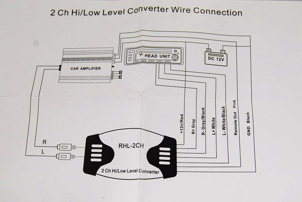
Wire Colors:
While the specific wire colors may vary slightly depending on the Metra LOC model, here are some common colors and their typical functions:
- White: Left Front Positive (+)
- White/Black: Left Front Negative (-)
- Gray: Right Front Positive (+)
- Gray/Black: Right Front Negative (-)
- Green: Left Rear Positive (+)
- Green/Black: Left Rear Negative (-)
- Purple: Right Rear Positive (+)
- Purple/Black: Right Rear Negative (-)
- Black: Ground
- Blue: Remote Turn-On (Optional)
How It Works
The Metra LOC essentially acts as a translator between your factory head unit and your aftermarket amplifier. Your factory head unit outputs a speaker-level signal, which has a relatively high voltage and current. Aftermarket amplifiers, on the other hand, are designed to accept a line-level signal, which has a much lower voltage and current.
The LOC takes the speaker-level signal from your factory speaker wires and converts it to a line-level signal that your amplifier can use. It does this through a network of resistors and capacitors that attenuate (reduce) the voltage of the signal. The impedance matching is a critical aspect of this conversion. The LOC is designed to present a suitable load to the factory amplifier and provide a low-impedance output for the aftermarket amplifier.
Real-World Use and Basic Troubleshooting
Let's say you've installed your Metra LOC, but you're not getting any sound from your amplifier. Here are some basic troubleshooting steps you can take using the wiring diagram:
- Verify the Ground Connection: A poor ground connection is the most common cause of audio problems. Ensure the ground wire from the LOC is securely connected to a clean, bare metal surface on the vehicle's chassis. Use a multimeter to check for continuity between the ground wire and the chassis.
A multimeter can be your best friend when troubleshooting electrical issues.
- Check the Speaker Wire Connections: Ensure that all the speaker wires are correctly connected to the factory speaker wires. Double-check the polarity (+/-) of each connection. Use the wiring diagram to verify that you've connected the correct wires.
- Verify the RCA Connections: Make sure the RCA cables are securely connected to both the LOC and the amplifier. Try swapping the RCA cables to see if the problem is with a faulty cable.
- Check the Remote Turn-On Wire: If your LOC has a remote turn-on wire, ensure it's properly connected to a switched 12V source (e.g., the accessory wire). Use a multimeter to verify that the remote turn-on wire is receiving 12V when the head unit is turned on.
- Adjust the Gain Knobs (If Applicable): If your LOC has adjustable gain knobs, try adjusting them to see if it improves the sound. Be careful not to set the gain too high, as this can cause distortion.
Safety Considerations
Working with car electrical systems can be dangerous. Here are some safety precautions to keep in mind:
- Disconnect the Battery: Before starting any wiring work, disconnect the negative terminal of your car battery. This will prevent accidental shorts and electrical shocks.
- Identify High-Risk Components: Be aware of components like the airbag system and the engine control unit (ECU). Avoid disturbing these components unless you're absolutely sure of what you're doing.
Working on the airbag system without proper training can be extremely dangerous.
- Use Proper Tools: Use insulated tools designed for automotive electrical work.
- Avoid Cutting Factory Wires: Whenever possible, use wire taps or T-taps to connect to factory wires. This will minimize the risk of damaging the factory wiring harness. If you must cut wires, ensure you use proper crimping tools and heat shrink tubing to create secure and insulated connections.
- Fuse Protection: Always use fuses to protect your wiring and equipment. Ensure the fuse rating is appropriate for the circuit you're protecting.
Remember to take your time and double-check your work. A little patience and attention to detail can go a long way in ensuring a successful installation.
We have a detailed, high-resolution wiring diagram available for download. This diagram will provide specific color codes and connection details for various Metra LOC models. Feel free to reach out and we can provide you with the file.