Wiring Diagram For Metra Line Output Converter Pdf
Let's talk about line output converters (LOCs) and their wiring diagrams, specifically those from Metra. Whether you're upgrading your car's audio system, fixing a faulty connection, or simply trying to understand how these things work, having a clear understanding of the wiring is crucial. This article will break down a typical Metra LOC wiring diagram, explain the symbols and colors, and offer practical advice for using it safely and effectively. We have a printable PDF version of the diagram available for you to download, ensuring you have this valuable resource at your fingertips.
Purpose of a Metra LOC Wiring Diagram
A Metra LOC wiring diagram is your roadmap to correctly connecting a line output converter to your car's factory radio. The diagram details the input and output connections, power supply, and ground. Without it, you risk miswiring the LOC, which could lead to poor audio quality, damage to your equipment, or even electrical fires. Specifically, the diagram serves these vital purposes:
- Installation: Guides the user on connecting the LOC to the correct speaker wires from the factory head unit.
- Troubleshooting: Helps diagnose issues like signal loss, distortion, or incorrect channel assignment.
- Repair: Assists in identifying and fixing broken or loose connections.
- Understanding: Provides insight into the LOC's internal circuitry and how it interacts with the car's audio system.
The diagram is beneficial whether you are a seasoned car audio enthusiast or a DIYer taking on your first project. Understanding it can save you time, money, and headaches.
Key Specs and Main Parts of a Metra LOC
Before diving into the wiring diagram, let's understand the components involved:
Key Specifications:
- Input Impedance: The resistance the LOC presents to the factory radio's speaker outputs (usually measured in Ohms).
- Output Impedance: The resistance the LOC presents to the aftermarket amplifier's inputs (usually lower than the input impedance).
- Input Voltage: The maximum voltage the LOC can handle from the factory speaker outputs. Exceeding this can damage the LOC.
- Output Voltage: The voltage the LOC outputs to the amplifier (often adjustable).
- Frequency Response: The range of frequencies the LOC can accurately reproduce.
- THD (Total Harmonic Distortion): A measure of the audio signal's distortion introduced by the LOC (lower is better).
Main Parts:
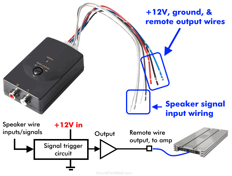
- Input Wires: These connect to the factory radio's speaker outputs. Typically, there are four input wires for two channels (left and right, positive and negative for each).
- Output RCA Jacks: These connect to the inputs of your aftermarket amplifier(s). Most LOCs have two RCA jacks for stereo output.
- Ground Wire: This must be securely connected to the car's chassis for proper operation and to prevent noise.
- Power Wire (Remote Turn-On): Some LOCs require a +12V switched power source. This signal usually activates the LOC, or some have a remote turn on output that turns on the amplifier. This is often labeled 'Remote Out' or 'REM'. The LOC uses the remote signal from the radio, or the LOC can generate its own signal when it detects a sound, and pass that signal to the amplifier to turn it on.
- Level Adjustment Knobs (Gain): These allow you to adjust the output signal level to match the input sensitivity of your amplifier.
Symbols and Colors in a Metra LOC Wiring Diagram
Understanding the symbols and colors used in the diagram is critical for accurate wiring. Here's a breakdown:
Lines:
- Solid Lines: Represent physical wires and connections.
- Dotted Lines: Might indicate shielding or optional connections. Always refer to the diagram's legend.
Colors:
While wire colors can vary slightly depending on the Metra LOC model and the vehicle's factory wiring, here are some common conventions. Always double-check the diagram's legend for your specific LOC model.
- Red: Typically +12V power.
- Black: Ground.
- White: Left channel positive (+) speaker wire.
- White/Black Stripe: Left channel negative (-) speaker wire.
- Gray: Right channel positive (+) speaker wire.
- Gray/Black Stripe: Right channel negative (-) speaker wire.
- Blue: Remote turn-on wire (output).
- Green: Rear Left channel positive (+) speaker wire.
- Green/Black Stripe: Rear Left channel negative (-) speaker wire.
- Purple: Rear Right channel positive (+) speaker wire.
- Purple/Black Stripe: Rear Right channel negative (-) speaker wire.
Icons:
- Ground Symbol (⏚): Indicates a connection to the vehicle's chassis for grounding. Ensuring a good ground is crucial for proper operation and noise reduction.
- RCA Jacks: Represent the audio outputs to the amplifier.
- Fuse Symbol: Indicates the location of an in-line fuse for circuit protection.
How a Metra LOC Works
The primary function of a Metra LOC is to convert the high-level speaker output from your factory head unit into a low-level RCA signal that your aftermarket amplifier can use. Factory head units often lack RCA outputs, so an LOC acts as an intermediary. This conversion is essential because amplifiers are designed to work with low-level signals.
Here's a simplified explanation of the process:
- The LOC receives the high-level speaker signals from the factory radio through its input wires.
- Inside the LOC, resistors and other components attenuate (reduce) the voltage of these signals.
- This attenuated signal is then converted into a low-level signal suitable for amplification.
- The LOC outputs this low-level signal through its RCA jacks, which are connected to the amplifier.
- The amplifier then boosts this signal to drive your aftermarket speakers or subwoofers.
Some LOCs also include features like remote turn-on generation, which automatically activates the amplifier when the factory radio is turned on, eliminating the need to tap into an ignition wire. The level adjustment knobs, or gain controls, allow you to fine-tune the output signal to match the input sensitivity of your amplifier, preventing clipping and distortion.
Real-World Use and Basic Troubleshooting
Here are some scenarios where the Metra LOC wiring diagram can be invaluable:
- Scenario 1: No Sound: If you've installed the LOC and have no sound, the first thing to check is the wiring. Use the diagram to ensure all wires are connected to the correct locations. Verify that the ground connection is secure and that the +12V power wire (if applicable) is receiving power. Check your fuses!
- Scenario 2: Distorted Sound: Distortion can be caused by incorrect gain settings. Use the LOC's level adjustment knobs to reduce the output signal until the distortion disappears. The wiring diagram will show where these gain controls are located. Double-check the input wires – are they connected to the correct speaker outputs from the head unit?
- Scenario 3: Noise (Hum or Whine): Noise is often caused by a poor ground connection. Ensure the ground wire is connected to a clean, bare metal surface on the car's chassis. Try a different grounding location if the noise persists. The diagram should help you verify the ground wire's proper placement.
- Scenario 4: Remote Turn-On Issues: If your amplifier isn't turning on automatically, check the remote turn-on wire. Use the diagram to verify that it's connected to the correct wire on the LOC (if it has a remote output). Also, ensure that the remote turn-on wire on your amplifier is properly connected.
Safety Precautions
Working with automotive electrical systems can be dangerous. Here are some essential safety precautions:
- Disconnect the Battery: Always disconnect the negative terminal of the car battery before working on any electrical components. This will prevent short circuits and potential injury.
- Use Proper Tools: Use insulated tools designed for automotive electrical work.
- Protect Wires: Use heat shrink tubing or electrical tape to insulate all connections and prevent shorts.
- Work in a Well-Ventilated Area: Avoid working in enclosed spaces where fumes from soldering or other chemicals can accumulate.
- Double-Check Your Work: Before reconnecting the battery, carefully review all connections to ensure they are correct and secure.
- Fuse Protection: Never bypass a fuse. If a fuse blows, identify and correct the underlying problem before replacing it with a fuse of the correct amperage rating. Improperly sized fuses are a common cause of electrical fires.
Remember that the factory radio and amplifier wiring can be very sensitive. Shorting the wrong wires can cause damage to the head unit or other electronic components.
By understanding the Metra LOC wiring diagram and following safe practices, you can confidently tackle your car audio upgrade projects. Remember to always consult the specific wiring diagram for your LOC model for the most accurate information.
Now that you're armed with this knowledge, you're ready to get started! As mentioned, we have the Metra Line Output Converter Wiring Diagram PDF available for you to download. Happy wiring!