
Wiring Diagram For Neutral Safety Switch
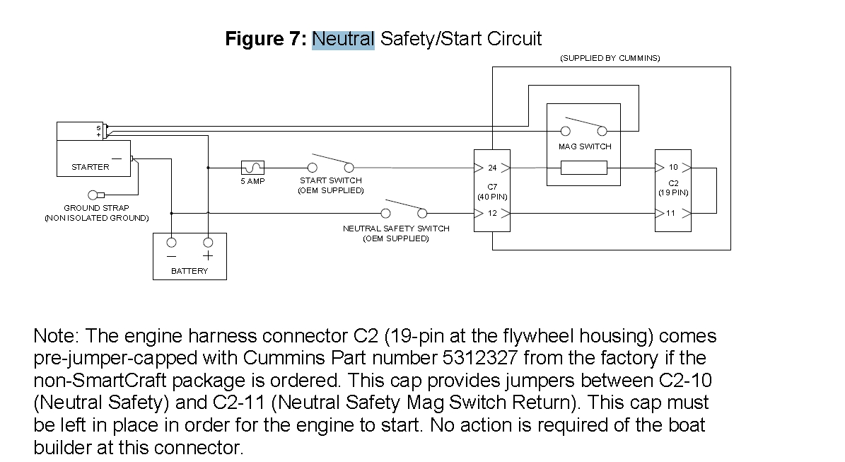
Alright, let's dive into the wiring diagram for a neutral safety switch (NSS). Understanding this diagram is crucial for a variety of tasks, from diagnosing why your car won't start to performing modifications or even just gaining a deeper understanding of your vehicle's electrical system. Whether you're tackling a repair, upgrading your transmission, or simply want to be a more informed car owner, this knowledge will serve you well.
Purpose and Importance
Why bother with a neutral safety switch diagram? The primary purpose is to understand how the NSS functions within your vehicle's starting circuit. The NSS, also sometimes called a transmission range sensor, is a critical safety device. Its main job is to prevent the engine from starting unless the transmission is in either Park (P) or Neutral (N). This prevents accidental starts that could cause the car to lurch forward or backward, potentially causing damage or injury. By understanding the wiring, you can diagnose issues like a no-start condition, intermittent starting problems, or even issues with your backup lights (which are often integrated into the NSS circuit).
Key Specs and Main Parts
Before we jump into the diagram itself, let's define some key components and specifications you'll encounter:
- Neutral Safety Switch (NSS) / Transmission Range Sensor (TRS): This is the heart of the system. It's typically mounted on the transmission and has internal contacts that change state based on the gear selector position.
- Starter Relay: This is an electromagnetic switch that allows a small current from the ignition switch and NSS to control a much larger current to the starter motor.
- Ignition Switch: The switch that activates the starting circuit when you turn the key to the "start" position.
- Starter Motor: The electric motor that cranks the engine.
- Battery: Provides the electrical power for the entire system.
- Ground: The return path for the electrical current, typically the vehicle's chassis.
- Fuses: Safety devices that protect the circuit from overcurrent.
You'll also encounter various wire gauges (e.g., 16 AWG, 14 AWG) which indicate the wire's current-carrying capacity. Knowing the wire gauge is important when replacing damaged wiring. Also note that the wiring diagram will specify the nominal voltage of the car, usually 12V or 24V.
Symbols – Deciphering the Diagram
Wiring diagrams use standardized symbols to represent electrical components and connections. Here's a breakdown of the most common ones you'll encounter in an NSS wiring diagram:
- Solid Lines: Represent wires. The thickness of the line doesn't necessarily indicate wire gauge, but it can sometimes be used to differentiate between power and signal wires.
- Dashed Lines: Often indicate a shielded wire or a connection that is optional or only present in certain configurations.
- Circles: Can represent a variety of components, depending on what's inside the circle. Could be a lamp, a relay coil, or a sensor.
- Squares/Rectangles: Typically represent electronic modules or control units.
- Ground Symbol: Usually looks like a series of decreasing horizontal lines connected to a vertical line, indicating a connection to the vehicle's chassis ground.
- Resistor Symbol: A jagged line representing a resistor.
- Capacitor Symbol: Two parallel lines, representing a capacitor.
- Relay Symbol: Shows both the coil and the switch contacts of the relay.
- Color Codes: Wires are often color-coded (e.g., Red for power, Black for ground, Blue for signal). The diagram will usually have a legend indicating the color codes used.
Pay close attention to the annotations on the diagram. These are text labels that identify components, wire numbers, connector numbers, and other important information. These annotations are crucial for tracing circuits and identifying the correct wires.
How It Works – The Electrical Path
Let's trace the typical circuit path for the NSS:
- When you turn the ignition key to the "start" position, voltage is applied to the ignition switch output.
- This voltage is then routed through the neutral safety switch. Crucially, the NSS only allows this voltage to pass if the transmission is in Park or Neutral. In other gear positions, the switch is open, breaking the circuit.
- If the NSS is closed (Park or Neutral), the voltage reaches the starter relay coil.
- The voltage energizes the starter relay coil, creating an electromagnetic field.
- This electromagnetic field pulls the relay's contacts closed, completing the circuit between the battery and the starter motor.
- The starter motor engages and cranks the engine.
The NSS wiring diagram will show all these connections and components in detail. You'll see the wires connecting the ignition switch, NSS, starter relay, and starter motor, along with the fuses and ground connections.
Real-World Use – Basic Troubleshooting
Understanding the NSS wiring diagram is invaluable for troubleshooting starting problems. Here are a few common scenarios and how the diagram can help:
- No Start in Park or Neutral: Use the diagram to check for voltage at the starter relay coil when the key is in the "start" position and the transmission is in Park or Neutral. If there's no voltage, trace the circuit back to the ignition switch and NSS to identify the break. Could be a faulty NSS, a broken wire, or a blown fuse.
- Car Starts in Gear: This is a dangerous situation! It likely indicates a faulty NSS that's not properly interrupting the circuit when the transmission is in gear. The diagram will help you locate the NSS and test its functionality. Replace the NSS immediately if you find this.
- Backup Lights Not Working: The backup light circuit is often integrated with the NSS. Use the diagram to identify the wires that control the backup lights and check for voltage when the car is in reverse.
- Intermittent Starting Problems: Sometimes, a loose connection or corroded terminal can cause intermittent starting issues. The diagram will help you identify all the connections in the NSS circuit and inspect them for corrosion or looseness.
When troubleshooting, use a multimeter to check for voltage and continuity. Continuity testing (checking if a circuit is complete) should only be done with the power off to avoid damaging your multimeter or vehicle's electrical system.
Safety – Handle with Care
Working with automotive electrical systems can be dangerous if you're not careful. Here are some important safety precautions:
- Disconnect the Battery: Always disconnect the negative battery terminal before working on any electrical components. This prevents accidental shorts and electrical shocks.
- Be Aware of High-Current Circuits: The starter motor circuit carries a very high current. Avoid touching any exposed wires in this circuit while the engine is cranking.
- Use Proper Tools: Use insulated tools designed for automotive electrical work.
- Protect Yourself: Wear safety glasses to protect your eyes from sparks or debris.
- Know Your Limits: If you're not comfortable working on electrical systems, take your car to a qualified mechanic.
The starter solenoid, often integrated into the starter motor, is another component that handles high currents. Be extremely cautious when working around it.
Remember, electricity always seeks the path of least resistance. Your body can become that path if you're not careful.
To get a detailed wiring diagram specific to your vehicle, you'll need to consult the manufacturer's service manual or a reputable online source. We have a generic neutral safety switch wiring diagram file available for download, which can serve as a general reference to aid understanding. It will provide a visual representation of the circuit, making it easier to trace wires and identify components. Armed with this diagram and the knowledge you've gained here, you'll be well-equipped to diagnose and repair NSS-related issues.