
Wiring Diagram For One Wire Alternator
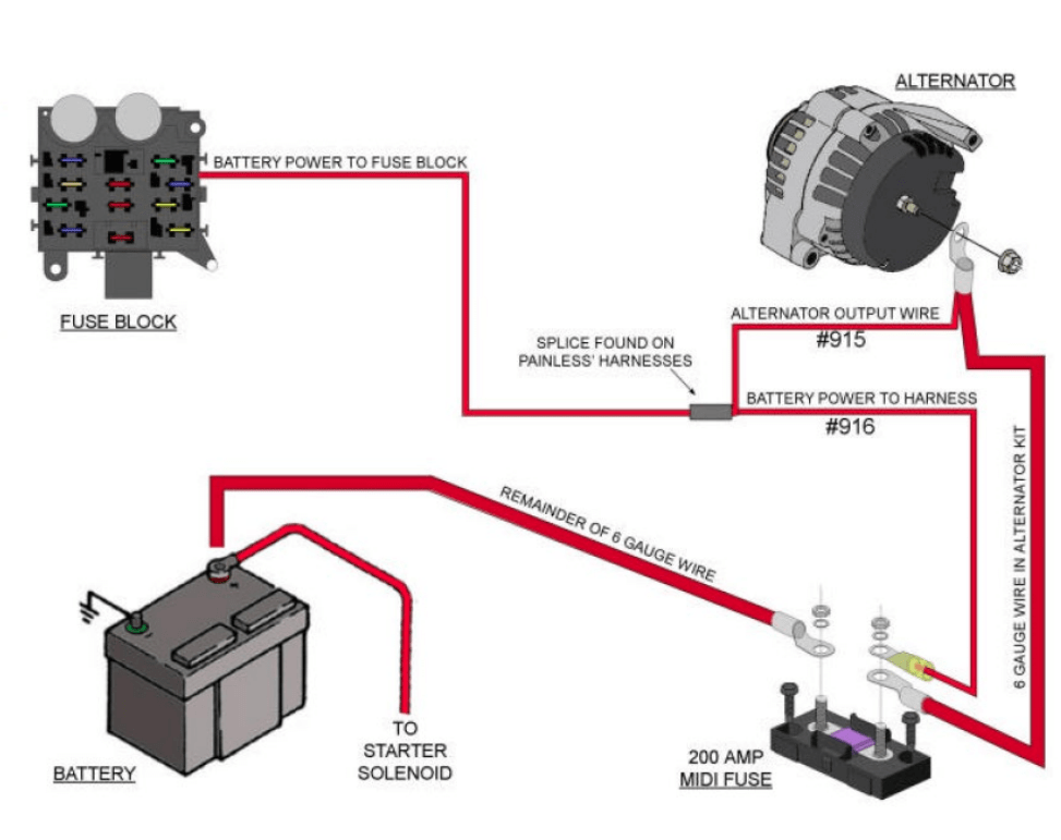
So, you're diving into the world of one-wire alternators? Excellent choice. They're simpler to wire, which makes them a popular upgrade for older vehicles, hot rods, or any project where you're looking for a cleaner engine bay. This article provides a comprehensive guide to understanding the wiring diagram for a one-wire alternator, covering everything from basic principles to troubleshooting tips. Think of it as your trusted mechanic explaining the ins and outs, but in written form.
Why Bother with a Wiring Diagram?
A wiring diagram isn't just a fancy picture; it's your roadmap for electrical systems. In the context of a one-wire alternator, understanding the diagram is crucial for several reasons:
- Repairs and Maintenance: When something goes wrong, a diagram helps you trace the circuit, identify faulty components, and troubleshoot issues efficiently. Without it, you're essentially guessing.
- Upgrades and Modifications: Swapping out a traditional alternator for a one-wire unit requires adapting the existing wiring. The diagram ensures you do it correctly, avoiding potential electrical damage or a non-functional charging system.
- Learning and Understanding: Even if you're not actively working on your car, studying the diagram provides a deeper understanding of how the charging system operates, making you a more knowledgeable DIYer.
- Safety: Incorrect wiring can lead to short circuits, fires, and other dangerous situations. A diagram helps you avoid these hazards.
Key Specs and Main Parts of a One-Wire Alternator System
Before we dive into the diagram itself, let's cover the key specs and components. This gives context to what you'll be seeing on the page.
- One-Wire Alternator: The star of the show. Unlike traditional alternators with multiple connections (sense wire, ignition wire, etc.), a one-wire alternator only needs a single wire connected to the battery. Internally, it's self-exciting, meaning it doesn't need an external voltage to start charging.
- Battery: The energy storage device. The alternator's job is to keep the battery charged. Pay close attention to battery voltage (usually 12V in automotive applications).
- Battery Cable: The thick wire connecting the alternator output to the positive terminal of the battery. This wire must be sized appropriately to handle the alternator's maximum output current. Undersized cables can overheat and cause a fire!
- Fuse or Circuit Breaker: A crucial safety component placed inline with the battery cable, as close as possible to the battery. It protects the system from overcurrent conditions. The amperage rating should be slightly higher than the alternator's maximum output.
- Ground Connection: The alternator housing must be securely grounded to the vehicle chassis. This provides a return path for the current. Clean, corrosion-free connections are essential for proper operation.
- Optional Voltmeter: While not strictly part of the core one-wire setup, a voltmeter allows you to monitor the charging system's performance.
Understanding the Wiring Diagram: Symbols and Conventions
Wiring diagrams use standardized symbols to represent electrical components and connections. Here's a breakdown of common symbols you'll encounter in a one-wire alternator diagram:
- Straight Lines: Represent wires. The thickness of the line may (but doesn't always) indicate the wire gauge (thickness).
- Dotted Lines: Often represent optional or less critical connections.
- Colors: Wires are often color-coded to aid in identification. Common colors include red (positive), black (ground), and other colors for specific signals. The diagram should include a key explaining the color coding.
- Battery Symbol: A series of short and long lines, often with a "+" and "-" symbol indicating polarity.
- Alternator Symbol: Varies depending on the diagram style, but usually a circle with the letters "ALT" or a stylized representation of the alternator.
- Fuse Symbol: A squiggly line enclosed in a rectangle.
- Circuit Breaker Symbol: Similar to a fuse, but with a reset mechanism indicated.
- Ground Symbol: A series of descending horizontal lines, indicating a connection to the vehicle chassis.
- Connections (Dots): Where lines intersect with a dot, it means they are electrically connected. Where lines cross without a dot, it typically means they are simply crossing paths and not connected.
Example Interpretation: A thick red line running from the alternator symbol to the battery symbol with a fuse symbol in between indicates the main charging wire, carrying positive voltage, protected by a fuse.
How a One-Wire Alternator Works: The Simplified Explanation
The beauty of a one-wire alternator lies in its simplicity. Here's the basic principle:
- Starting Up: When the engine starts, the alternator initially relies on residual magnetism within its rotor to generate a small voltage. This is why one-wire alternators often require a brief "rev" to get them charging initially.
- Self-Excitation: Once the alternator starts producing a small voltage, it uses a portion of its own output to increase the magnetic field in the rotor, which in turn increases the output voltage. This is called self-excitation.
- Voltage Regulation: An internal voltage regulator monitors the output voltage and adjusts the field current to maintain a stable charging voltage (typically around 13.8-14.7 volts). This prevents overcharging the battery.
- Charging the Battery: The regulated voltage is sent through the single output wire to the battery, replenishing the charge lost during starting and running electrical accessories.
- Grounding: The alternator's housing must be properly grounded to the vehicle chassis to complete the circuit and allow current to flow back to the battery's negative terminal.
Real-World Use: Basic Troubleshooting Tips
Even with a simplified system, problems can occur. Here are some basic troubleshooting steps you can perform using the wiring diagram as your guide:
- No Charging: Use a voltmeter to check the voltage at the alternator output terminal. If it's the same as battery voltage, the alternator isn't charging. Check the battery cable and fuse for continuity. Also, confirm that the alternator is properly grounded. If you suspect a bad fuse, inspect and replace the fuse. If fuse is good, consider seeking professional help.
- Overcharging: If the voltage is significantly higher than 14.7 volts, the voltage regulator is likely faulty. Replace the alternator.
- Erratic Voltage: Fluctuating voltage readings can indicate a loose connection, a corroded ground, or a failing voltage regulator. Inspect all connections and clean them as needed.
- Fuse Blows Repeatedly: This indicates a short circuit in the wiring. Carefully inspect the entire length of the battery cable for damage or frayed insulation. Also, make sure the cable is properly sized for the alternator's output.
- Alternator Not Initially Exciting: Some alternators don't excite until engine rpm is around 1500. Some may be defective or can be fixed with a small 12v supply to excite it initially.
Safety First: Handling High-Current Circuits
Working with automotive electrical systems involves inherent risks. Here are some crucial safety precautions:
- Disconnect the Battery: Always disconnect the negative battery terminal before working on any electrical components. This prevents accidental short circuits.
- Use Properly Insulated Tools: Protect yourself from electric shock by using tools with insulated handles.
- Wear Safety Glasses: Protect your eyes from flying debris or sparks.
- Handle Fuses and Circuit Breakers Carefully: Never bypass a fuse or circuit breaker. They are there to protect the system from overcurrent conditions.
- Work in a Well-Ventilated Area: Battery acid can produce harmful fumes.
- Seek Professional Help When Needed: If you're not comfortable working with electrical systems, consult a qualified mechanic. High-current circuits can be dangerous if not handled properly. Never work on the electrical system with the engine running!
One-wire alternators can greatly simplify an electrical system, but understanding the underlying wiring and principles is critical for successful installation and troubleshooting. This guide provides the foundational knowledge you need. Remember to always prioritize safety and consult with a professional if you're unsure about any aspect of the process.
We have a detailed, downloadable wiring diagram available. It contains all the information discussed here, plus specific values and component recommendations. Let us know if you want to access it.