
Wiring Diagram For Points Distributor
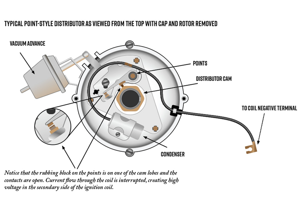
The venerable points distributor, a cornerstone of internal combustion engine ignition systems for decades, might seem archaic in today's world of electronic ignition. However, understanding its wiring and function remains incredibly valuable. Whether you're maintaining a classic car, learning the fundamentals of ignition systems, or even experimenting with alternative fuel setups, a solid grasp of the points distributor is essential. This article will provide a detailed breakdown of a typical points distributor wiring diagram, equipping you with the knowledge to diagnose issues, perform repairs, and understand the underlying principles.
Purpose of Understanding the Wiring Diagram
Why bother understanding the wiring of a system that's largely been superseded? The answer is multifaceted:
- Diagnostics: Even if you don't work on vintage cars regularly, the troubleshooting techniques learned from diagnosing points systems are transferable to more modern, electronically controlled ignition systems.
- Repair and Maintenance: Many classic vehicles still rely on points distributors. Knowing the wiring allows you to perform maintenance like replacing condensers or adjusting points gap with confidence.
- Learning the Fundamentals: Points distributors offer a clear, mechanically driven example of how ignition timing works. It’s an excellent learning tool for understanding the entire combustion process.
- Modification and Customization: Hot rodders and engine builders often modify and adapt points systems for specific performance goals or to integrate with aftermarket components. A wiring diagram is indispensable for this.
- Historical Knowledge: Appreciating the evolution of automotive technology requires understanding the systems that paved the way for modern advancements.
Key Specs and Main Parts
Before diving into the diagram, let's define the key components and specifications commonly found in a points distributor ignition system:
Main Parts:
- Distributor Body: The housing containing all the internal components.
- Distributor Cap: Directs the high-voltage spark to the correct spark plug.
- Rotor: A rotating arm inside the distributor cap that distributes the spark.
- Points (Contact Points): A mechanical switch that opens and closes to interrupt the primary ignition circuit. Critical for timing and spark generation.
- Condenser (Capacitor): Absorbs voltage spikes when the points open, preventing arcing and prolonging points life.
- Distributor Shaft: Driven by the engine, rotating the points cam and rotor.
- Points Cam: A lobed cam that opens and closes the points as the distributor shaft rotates.
- Centrifugal Advance Mechanism: Weights and springs that advance the ignition timing based on engine speed (RPM).
- Vacuum Advance Unit: A diaphragm linked to the intake manifold vacuum that advances the ignition timing based on engine load.
- Primary Wire (Coil - to - Points): Connects the negative terminal of the ignition coil to the points.
- Ground Wire: Grounds the distributor body to the engine block.
Key Specifications:
- Dwell Angle: The number of degrees of distributor shaft rotation that the points remain closed. This directly affects the coil saturation time.
- Points Gap: The physical distance between the points when they are fully open. Properly setting the points gap is crucial for correct dwell angle.
- Firing Order: The sequence in which the cylinders fire in the engine. This dictates the arrangement of spark plug wires on the distributor cap.
- Ignition Timing (Base Timing): The timing of the spark relative to piston position (typically expressed in degrees BTDC - Before Top Dead Center).
- Coil Primary Resistance: The resistance of the primary winding of the ignition coil. This is important for matching the coil to the ignition system (especially when using an external resistor).
Symbols in the Wiring Diagram
Understanding the symbols used in the wiring diagram is crucial for proper interpretation. Here's a breakdown of common symbols:
- Solid Lines: Represent wires. Thicker lines often indicate heavier gauge wires, carrying higher current.
- Dashed Lines: May represent mechanical linkages (e.g., vacuum advance hose) or shielded wires.
- Circles with a "X" inside: Represent wire splices or junctions.
- Ground Symbol (Typically three horizontal lines decreasing in length): Indicates a connection to the chassis or engine block (ground).
- Coil Symbol (Inductor): A coil of wire, representing the ignition coil.
- Capacitor Symbol (Two parallel lines): Represents the condenser.
- Switch Symbol: Shows the points as a switch that opens and closes.
- Battery Symbol: Indicates the car battery, with positive (+) and negative (-) terminals.
Color Coding: Wire colors are essential for tracing circuits. Standard color codes vary by manufacturer and year, but commonly used colors include:
- Red: Typically used for power wires connected to the battery (+12V).
- Black: Typically used for ground wires.
- Green: Often used for wires connected to sensors (e.g., temperature sensors).
- Blue/Yellow: Common for ignition-related circuits.
- Consult your vehicle's specific wiring diagram to confirm color codes.
How It Works: The Ignition Cycle
To fully understand the wiring diagram, it's essential to understand the ignition cycle:
- Points Closed (Dwell): With the points closed, the primary circuit is completed, allowing current to flow from the battery, through the ignition switch, through the primary winding of the ignition coil, and finally to ground through the closed points. This current flow builds up a strong magnetic field in the coil.
- Points Open (Firing): As the distributor shaft rotates, the points cam causes the points to open. This rapidly interrupts the primary circuit, causing the magnetic field in the ignition coil to collapse.
- Voltage Induction: The collapsing magnetic field induces a very high voltage (typically 20,000 - 40,000 volts) in the secondary winding of the ignition coil.
- Spark Distribution: This high-voltage spark travels from the coil, through the distributor cap, to the rotor, and then to the correct spark plug based on the engine's firing order.
- Combustion: The spark ignites the air-fuel mixture in the cylinder, initiating combustion.
- Condenser Function: The condenser absorbs the voltage spike generated when the points open, preventing arcing across the points and protecting them from premature wear.
Real-World Use: Basic Troubleshooting Tips
Here are some common problems associated with points distributors and how the wiring diagram can help you troubleshoot them:
- No Spark:
- Check for voltage at the positive (+) terminal of the ignition coil with the ignition switch on. If no voltage, check the ignition switch and wiring.
- Inspect the points for corrosion or damage. Clean or replace them if necessary.
- Verify that the points are opening and closing properly. Adjust the points gap if needed.
- Test the condenser. A faulty condenser can cause a weak or nonexistent spark.
- Use a multimeter to check the resistance of the ignition coil primary and secondary windings. Out-of-spec resistance indicates a faulty coil.
- Weak Spark:
- Check the points gap and dwell angle. Incorrect dwell can lead to a weak spark.
- Inspect the distributor cap and rotor for cracks or carbon tracking.
- Check for loose or corroded connections in the ignition circuit.
- Test the ignition coil.
- Engine Misfire:
- Check the spark plug wires for proper connection and resistance.
- Inspect the spark plugs for fouling or damage.
- Verify the engine's timing is correct.
- Look for vacuum leaks that could affect the vacuum advance unit.
Using the Wiring Diagram for Troubleshooting: The wiring diagram allows you to trace the circuit from the battery, through the ignition components, and back to ground. This helps you identify potential points of failure, such as broken wires, loose connections, or short circuits. A multimeter is your best friend for confirming voltage and resistance at various points in the circuit.
Safety Considerations
Working on ignition systems involves high voltage. Here are some crucial safety precautions:
- Disconnect the Battery: Before working on any electrical component, disconnect the negative (-) terminal of the battery to prevent accidental shocks or shorts.
- Avoid Contact with High-Voltage Components: Never touch the spark plug wires, distributor cap, or ignition coil while the engine is running. The high voltage can deliver a dangerous shock.
- Work in a Well-Ventilated Area: Fuel vapors are flammable and explosive. Ensure proper ventilation when working around the engine.
- Use Insulated Tools: Always use insulated tools when working on electrical components.
- Be Especially Careful with the Condenser: Although small, the condenser can store a significant charge even after the engine is off. Ground the condenser before handling it to discharge any stored voltage.
The points distributor, while relatively simple in design, requires a thorough understanding of its wiring and operation for effective maintenance and troubleshooting. With the knowledge gained from this article and a clear wiring diagram in hand, you'll be well-equipped to tackle most points distributor-related issues. Remember to always prioritize safety when working with electrical components and consult your vehicle's specific service manual for detailed instructions and specifications. Now that you're armed with this knowledge, you can confidently diagnose, repair, and even modify points distributor ignition systems!
We have a sample wiring diagram file available for download. It provides a visual reference to reinforce the concepts discussed in this article.