Wiring Diagram For Schumacher Battery Charger
Welcome, gearheads! Today, we're diving deep into the wiring diagram of a Schumacher battery charger. Whether you're troubleshooting a malfunctioning charger, modifying one for a specific project, or simply aiming to understand its inner workings, a solid grasp of the wiring is essential. This guide will break down the complex diagram into manageable chunks, arming you with the knowledge to confidently tackle repairs and modifications.
Purpose of Understanding the Wiring Diagram
Why bother with the wiring diagram? Well, imagine your battery charger suddenly stops charging. Instead of blindly replacing parts, the diagram allows you to trace the circuit, identify faulty components like diodes or transformers, and pinpoint the exact cause of the problem. This not only saves you money but also prevents potential hazards. Furthermore, if you're thinking of upgrading the charging amperage or adding custom features, the wiring diagram provides the blueprint for safe and effective modifications. It's like having the instruction manual for the charger's electrical system.
Key Specs and Main Parts
Before we delve into the diagram, let's identify the critical components typically found in a Schumacher battery charger. Understanding their purpose is vital for deciphering the wiring.
- Transformer: This is the heart of the charger, stepping down the AC voltage from your wall outlet (typically 120V AC) to a lower AC voltage suitable for charging batteries (e.g., 12V AC).
- Rectifier (Diodes/Bridge Rectifier): Converts the AC voltage from the transformer into DC voltage, which is required for charging batteries. Diodes are semiconductor devices that allow current to flow in only one direction. A bridge rectifier utilizes four diodes to efficiently convert AC to DC.
- Ammeter/Voltmeter: These meters display the charging current (amps) and voltage, respectively, providing feedback on the charging process. Some chargers have digital displays, while others use analog meters.
- Charging Leads (Positive and Negative): These cables connect the charger to the battery terminals. They are usually color-coded (red for positive, black for negative).
- Clamps/Connectors: These provide a secure connection to the battery terminals.
- Fuses/Circuit Breakers: These are safety devices that protect the charger from overloads and short circuits. They are designed to interrupt the current flow if it exceeds a safe level.
- Switches/Selectors: These allow you to select different charging modes (e.g., slow charge, fast charge, boost).
- Capacitors: Used for filtering and smoothing the DC voltage output, reducing ripple.
- Resistors: Used to limit current and divide voltage in various parts of the circuit.
- Control Circuitry (Microcontroller, if present): In modern smart chargers, a microcontroller manages the charging process, adjusting the voltage and current based on the battery's condition and the selected charging mode.
Symbols – Understanding the Language of the Diagram
Wiring diagrams use standardized symbols to represent electrical components and connections. Learning these symbols is crucial for interpreting the diagram accurately.
- Solid Lines: Represent wires or conductors. The thickness of the line doesn't necessarily indicate wire gauge.
- Dotted Lines: Often represent shielding or a mechanical connection (e.g., a linkage that is not electrical).
- Circles: Can represent a variety of components depending on what's inside. For example, a circle with an "A" inside typically represents an ammeter, and a circle with a "V" represents a voltmeter.
- Resistor: Represented by a jagged line or a rectangle.
- Capacitor: Two parallel lines, often curved.
- Diode: A triangle pointing to a line. The direction of the triangle indicates the direction of current flow.
- Transformer: Two coils of wire (usually represented by a symbol resembling linked "U" shapes) separated by parallel lines (representing the core).
- Fuse: A line with a break in the middle or a rectangle with a zigzag inside.
- Switch: A line that can be connected or disconnected from another line.
- Ground: Usually represented by three horizontal lines, getting progressively shorter. Indicates a connection to earth ground or a common reference point.
- Colors: Wires are often color-coded in the diagram, and these colors correspond to the actual wire colors in the charger. Common colors include:
- Black: Typically ground or negative.
- Red: Typically positive.
- White: Often neutral in AC circuits.
- Green: Typically earth ground.
Remember that the specific symbols and color conventions might vary slightly between different manufacturers and diagrams. However, the basic principles remain the same.
How It Works: A Simplified Explanation
Let's break down the charging process based on the wiring. The AC voltage from the wall outlet enters the charger and is fed into the transformer. The transformer steps down the voltage to the appropriate level for charging the battery (e.g., 12V AC). The AC voltage then passes through the rectifier (typically a bridge rectifier using diodes), which converts it into DC voltage. The DC voltage is then filtered by capacitors to smooth out any ripples. The charging current and voltage are displayed on the ammeter and voltmeter, respectively. Finally, the DC voltage is applied to the battery through the charging leads (positive and negative). The control circuitry (if present) monitors the battery's voltage and current, adjusting the charging process as needed to prevent overcharging or damage.
Real-World Use: Basic Troubleshooting Tips
Okay, your charger is acting up. Here are some basic troubleshooting tips using the wiring diagram:
- Charger won't turn on: Check the power cord for damage. Use a multimeter to test for voltage at the input of the transformer. If there's no voltage, the problem is likely in the power cord, switch, or input fuse.
- Charger turns on but doesn't charge: Check the output voltage of the transformer. If there's no output voltage, the transformer is likely faulty. Use a multimeter to test the diodes in the rectifier. A faulty diode will prevent proper DC conversion. Also, check the output fuse (if present) to make sure it isn’t blown.
- Ammeter shows no current: Check the charging leads and clamps for damage or corrosion. Use a multimeter to test for continuity between the charger's output terminals and the battery terminals. Make sure the battery is capable of accepting a charge.
- Overheating: Check for proper ventilation. Excessive heat can indicate a faulty transformer, diodes, or other components.
Safety – Handle with Care!
Working with electrical circuits can be dangerous. Always disconnect the charger from the power outlet before opening it up or working on the wiring. The transformer and capacitors can store potentially lethal voltages even after the charger is unplugged. Discharge capacitors carefully with a resistor before touching them. If you are not comfortable working with electrical circuits, consult a qualified electrician.
High-voltage components are present inside the charger, especially the transformer and primary side of the circuit. Never touch these components while the charger is plugged in. Even after unplugging, capacitors can retain a charge, so discharge them before touching any components.
Warning: Modifying the charger beyond its intended specifications can be hazardous and may void any warranties. Always exercise caution and consult with an expert if you are unsure about any modifications.
By understanding the wiring diagram, you can confidently diagnose and repair your Schumacher battery charger, extending its lifespan and saving you money. You now have a solid foundation for tackling basic repairs and modifications, always keeping safety a top priority.
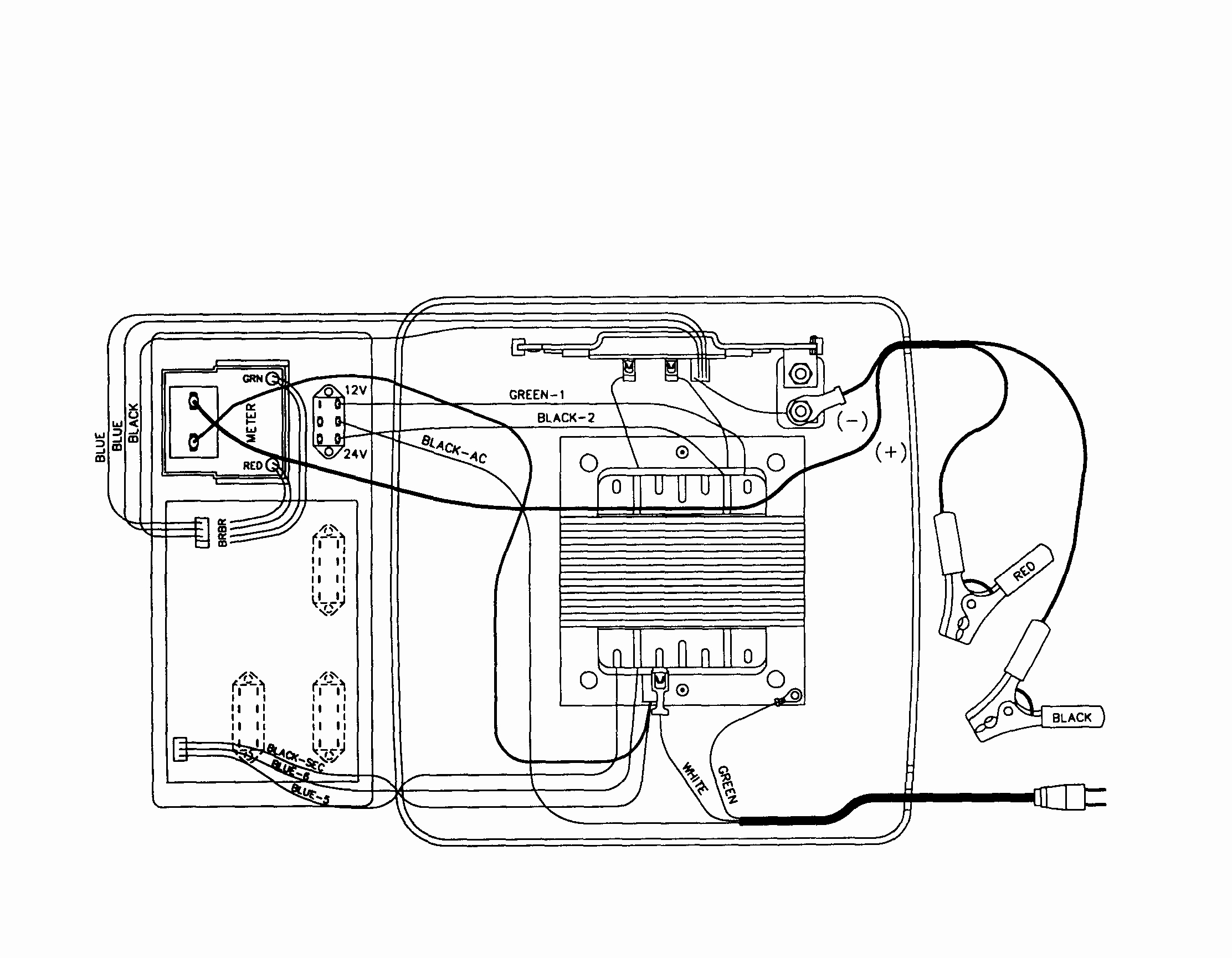
We have a sample wiring diagram file available for download. This diagram provides a visual representation of the information discussed in this article. This will help you apply the concepts learned to a real-world example.