Wiring Diagram For Semi Trailer Plug
So, you're diving into the world of semi-trailer wiring? Excellent! Understanding your semi-trailer plug wiring is crucial whether you're tackling repairs, adding accessories, or simply want a deeper understanding of your vehicle's electrical system. This article will break down a typical semi-trailer plug wiring diagram, giving you the knowledge and confidence to approach these tasks safely and effectively. We'll focus on the ubiquitous 7-way round pin connector, also known as the SAE J560 connector, as it's the industry standard.
Why This Diagram Matters
Think of your semi-trailer plug as the vital communication link between the tractor and the trailer. It's not just about lights; it's about brakes, signals, and sometimes even auxiliary power. A faulty connection can lead to serious safety issues, including brake failure, inoperable lights (leading to fines and accidents), or drained batteries. A good wiring diagram allows you to:
- Troubleshoot Electrical Issues: Pinpoint shorts, opens, and incorrect wiring.
- Perform Repairs: Replace damaged wires or connectors with confidence.
- Add Accessories: Wire in new lights, auxiliary power outlets, or other electrical components.
- Ensure Compliance: Verify that your trailer wiring meets DOT regulations.
- Deepen Understanding: Gain a solid grasp of how your trailer's electrical system functions.
Key Specs and Main Parts
Before we dive into the diagram itself, let's cover the key specifications and components of a typical 7-way round pin connector system:
- Connector Type: SAE J560 7-way round pin (industry standard)
- Voltage: Typically 12V DC
- Wire Gauge: Varies depending on the circuit, but 12-16 gauge is common. Refer to your specific trailer's wiring diagram for exact gauges.
- Main Components:
- Tractor-Side Connector (Pigtail): The connector attached to the tractor.
- Trailer-Side Connector: The connector on the trailer itself.
- Wiring Harness: The bundle of wires connecting the connectors to the various components on the trailer.
Symbols: Understanding the Language of the Diagram
A wiring diagram uses symbols and conventions to represent electrical components and their connections. Here's a breakdown of what you'll commonly see:
- Lines: Solid lines represent wires. Dashed lines may indicate optional connections or grounds. Line thickness doesn't necessarily correlate to wire gauge.
- Colors: Each wire is assigned a specific color to aid in identification. Common colors include:
- White: Ground
- Brown: Tail Lights
- Yellow: Left Turn/Stop
- Green: Right Turn/Stop
- Red: Stop Lights
- Black: 12V Power (Auxiliary/Battery Charge)
- Blue: Electric Brakes
- Circles with Numbers: These represent the pins within the connector. Each pin corresponds to a specific circuit.
- Ground Symbol: Typically three horizontal lines decreasing in size. Indicates a connection to the vehicle's chassis for grounding.
- Component Symbols: Simplified representations of lights, brakes, and other electrical components. These vary depending on the diagram's complexity, but a rectangle with an "X" often signifies a light.
- Connectors: Often depicted as interlocking shapes showing how wires connect.
- Splices: Places where two or more wires are joined together.
Important Note: Color codes can sometimes vary slightly between manufacturers and even between different years of the same trailer model. Always double-check your specific wiring diagram before making any connections.
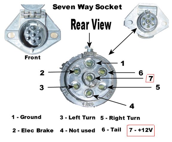
Typical 7-Way Connector Pinout:
This is a general guide; always refer to your specific diagram.
- Ground (White)
- Tail Lights (Brown)
- Left Turn/Stop (Yellow)
- Right Turn/Stop (Green)
- Stop Lights (Red)
- 12V Power (Auxiliary/Battery Charge) (Black)
- Electric Brakes (Blue)
How It Works: The Electrical Flow
The 7-way connector facilitates the transfer of electrical signals from the tractor to the trailer. Here's a simplified explanation of how the key circuits function:
- Ground (White): Provides a return path for the electrical current, completing the circuit. A solid ground connection is critical for proper operation.
- Tail Lights (Brown): Powers the tail lights when the tractor's headlights are activated.
- Left/Right Turn/Stop (Yellow/Green): Carries the signals for the left and right turn signals and brake lights. When you activate the turn signal or press the brake pedal, the corresponding signal is sent through this wire.
- Stop Lights (Red): Separate stop light circuit for enhanced safety and visibility. These illuminate only when the brake pedal is depressed.
- 12V Power (Black): Provides a constant 12V power source to the trailer. This can be used to charge a trailer battery, power interior lights, or operate other auxiliary equipment. Caution: Ensure proper fusing to protect this circuit from overloads.
- Electric Brakes (Blue): Sends a signal to the trailer's electric brake controller, which then applies the brakes. The amount of braking force is typically proportional to the signal strength.
Real-World Use: Basic Troubleshooting Tips
Now let's talk about putting this knowledge into action. Here are some basic troubleshooting tips:
- Start with the Basics: Check the fuses on both the tractor and the trailer. A blown fuse is the most common cause of electrical problems.
- Visual Inspection: Inspect the connectors for corrosion, damaged pins, or loose wiring. Clean corroded connectors with electrical contact cleaner.
- Test for Voltage: Use a multimeter to check for voltage at each pin on the trailer-side connector when the corresponding circuit is activated on the tractor. For example, check for voltage on the yellow pin when the left turn signal is on.
- Check the Ground: A poor ground connection is a frequent culprit. Ensure that the ground wire is securely attached to a clean, unpainted metal surface on both the tractor and the trailer.
- Use a Test Light: A test light can be used to quickly check for power at various points in the circuit.
- Isolate the Problem: If you're experiencing problems with a specific circuit, try disconnecting the trailer from the tractor and testing the trailer's wiring independently. This will help you determine whether the problem lies on the tractor or the trailer side.
Safety: Handling Risky Components
Working with electrical systems can be dangerous if you don't take proper precautions. Keep these safety tips in mind:
- Disconnect the Power: Always disconnect the trailer from the tractor and disconnect the battery (if applicable) before working on the wiring.
- Use Proper Tools: Use insulated tools designed for electrical work.
- Wear Safety Glasses: Protect your eyes from sparks and debris.
- Be Aware of Short Circuits: Avoid creating short circuits, which can damage your electrical system and cause fires.
- Fuses Are Your Friend: Always replace blown fuses with fuses of the same amperage rating. Never use a fuse with a higher rating, as this can overload the circuit and cause a fire.
- High Voltage Lines: While the 7-way is low voltage, be careful around high voltage power lines above the trailer when in operation.
Especially pay attention to the 12V Power (Black) wire. This wire provides a direct connection to the battery and can deliver a significant amount of current. A short circuit on this wire can quickly lead to a fire. Ensure that this circuit is properly fused and that the wiring is in good condition.
By following this information and using the correct wiring diagram, you can repair most wiring issues yourself. Remember, when it comes to brakes, if you are not comfortable, seek assistance from a professional.
We have a detailed wiring diagram available for download, tailored to common semi-trailer setups. This diagram includes specific color codes, component locations, and troubleshooting tips. This diagram will make the process of troubleshooting and repairing your trailer wiring much easier. Feel free to reach out for the download link.