
Wiring Diagram For Single Light Switch
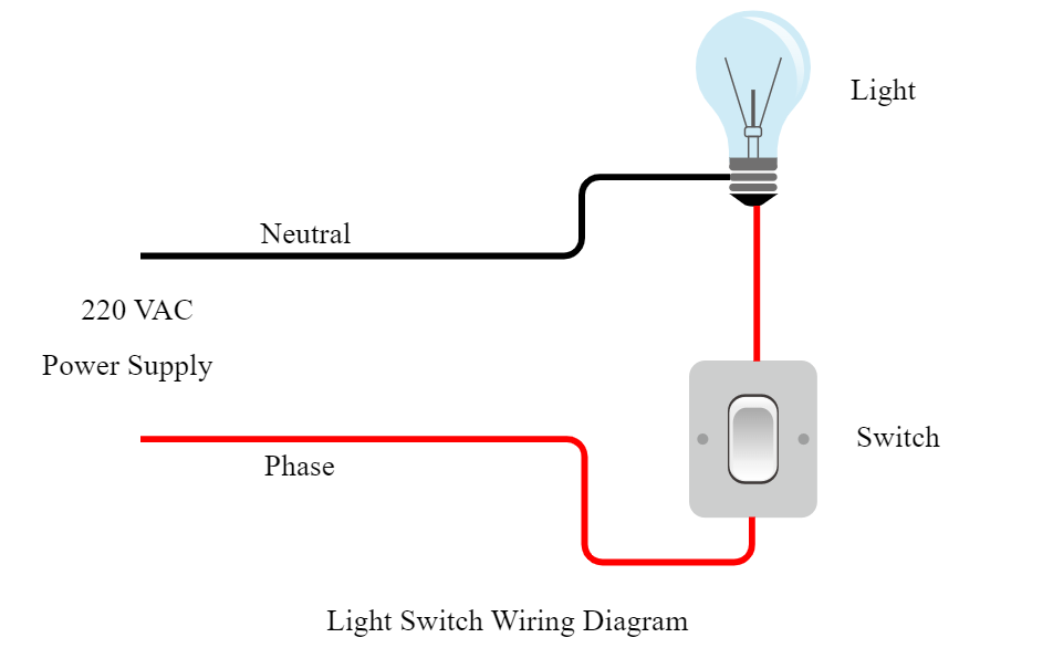
Alright, let's dive into something fundamental but often overlooked: the wiring diagram for a single light switch. Whether you're diagnosing a faulty circuit in your car, planning a custom lighting mod, or just aiming to deepen your electrical understanding, grasping this basic diagram is crucial. We're not talking about rocket science here, but a solid foundation will prevent future headaches and, more importantly, keep you safe.
Purpose: Why This Diagram Matters
Why bother learning about this? Simply put, understanding this wiring diagram empowers you to:
- Troubleshoot Electrical Issues: Identify breaks in the circuit, shorts, or faulty components. Is your dome light flickering? This diagram is your starting point.
- Plan Custom Mods: Adding aftermarket lighting? You *need* to know how to properly wire it in. Blindly connecting wires is a recipe for disaster.
- Perform Repairs Safely: Before replacing a switch or wiring, understanding the circuit’s layout will ensure you reconnect everything correctly and avoid electrical hazards.
- Gain a Deeper Understanding: Electrical systems are complex, but mastering the basics – like this light switch circuit – is the first step towards understanding more advanced automotive electronics.
Key Specs and Main Parts
Let's break down the essential components and their roles. This is a simplified circuit, but the principles apply across more complex setups.
- Power Source (Battery): Typically, your car's 12V battery provides the electrical energy. This is the "positive" or "+" side of the circuit. We'll see this represented as a voltage source in the diagram.
- Fuse: A critical safety device. The fuse is a sacrificial element designed to blow (open the circuit) if the current exceeds a safe level. This protects the wiring and components from overheating and potentially causing a fire. Think of it as a pressure relief valve for electricity. A blown fuse is a symptom, not the problem itself. Always investigate *why* it blew.
- Switch (Single-Pole, Single-Throw - SPST): The most common type of light switch. It has two terminals and simply connects or disconnects the circuit. Think of it as a gate – open (off) or closed (on).
- Load (Light Bulb): The device that consumes the electrical energy and performs a function (in this case, emits light). Its resistance determines the current flow in the circuit.
- Wiring: Copper wires that provide the conductive path for the current to flow. Wire gauge (thickness) is important! Too thin, and the wire can overheat and melt under heavy current.
- Ground (Chassis Ground): The "negative" or "-" side of the circuit. In automotive systems, the chassis (metal frame) of the car often serves as the ground path, completing the circuit back to the battery. This simplifies wiring and reduces the amount of wire needed.
Symbols: Lines, Colors, and Icons
Wiring diagrams use standardized symbols to represent components and connections. Understanding these symbols is key to interpreting the diagram correctly.
- Solid Line: Represents a wire. The thickness of the line *usually* doesn't indicate wire gauge, but always refer to the circuit's specifications.
- Dashed Line: May represent a shielded wire or a connection that's not directly part of the main circuit (e.g., a ground connection to the chassis).
- Colors: Color-coding of wires is crucial for identification. Common colors include:
- Red: Usually indicates a positive (+) power supply.
- Black: Usually indicates ground (-).
- Other Colors (Blue, Green, Yellow, White, etc.): Used for various signal and control wires. Refer to the specific vehicle's wiring diagram for the exact color-coding scheme.
- Fuse Symbol: A jagged line, often enclosed in a rectangular box. The amperage rating (e.g., 10A, 20A) is usually indicated next to the symbol.
- Switch Symbol (SPST): Two circles (terminals) with a line that can connect or disconnect them.
- Light Bulb Symbol: A circle with an "X" inside, or a stylized representation of a light bulb filament.
- Ground Symbol: Several parallel lines decreasing in length, resembling an upside-down pyramid. This indicates a connection to the chassis ground.
- Battery Symbol: A series of short and long parallel lines. The longer line represents the positive (+) terminal, and the shorter line represents the negative (-) terminal.
How It Works
Let's trace the flow of electricity in the circuit:
- Current flows from the battery's positive (+) terminal, through the fuse.
- The fuse protects the circuit from overcurrent. If the current exceeds its rating, the fuse blows, opening the circuit.
- From the fuse, the current flows to one terminal of the switch.
- When the switch is closed (ON), it connects the circuit, allowing current to flow from the switch to the light bulb.
- The light bulb consumes the electrical energy and emits light.
- From the light bulb, the current flows to ground (the chassis of the car).
- Finally, the current flows back to the battery's negative (-) terminal, completing the circuit.
With the switch open (OFF), the circuit is broken, and no current flows, so the light bulb doesn't light up.
Real-World Use: Basic Troubleshooting Tips
Here's how you can use your understanding of the wiring diagram to diagnose common problems:
- Light Doesn't Turn On:
- Check the Fuse: Is it blown? Replace it with one of the same amperage rating. If it blows immediately after replacement, there's a short circuit somewhere.
- Check the Bulb: Is the filament broken? Replace the bulb.
- Check the Switch: Use a multimeter (a device that measures voltage, current, and resistance) to check if the switch is working correctly. With the switch in the ON position, there should be continuity (low resistance) between the terminals.
- Check the Wiring: Look for any broken or damaged wires. Use a multimeter to check for voltage at the light bulb socket.
- Check the Ground Connection: Ensure the ground connection is clean and secure. A loose or corroded ground connection can cause all sorts of electrical problems.
- Light Stays On:
- Check the Switch: The switch might be stuck in the ON position, even when physically switched off. Replace the switch.
- Short Circuit: There might be a short circuit somewhere in the wiring, bypassing the switch. This requires careful inspection of the wiring harness.
Safety: Highlight Risky Components
Working with electrical systems involves inherent risks. Be aware of the following:
- Battery: Disconnect the negative battery terminal before working on any electrical components. This prevents accidental short circuits and potential shocks.
- Fuses: Never replace a fuse with one of a higher amperage rating. This can overload the wiring and components, leading to overheating and fire.
- Wiring: Damaged wiring can expose live conductors, posing a shock hazard. Repair or replace damaged wiring promptly.
- Short Circuits: A short circuit occurs when current flows through an unintended path, bypassing the load (e.g., the light bulb). This can cause a large current flow, overheating, and fire. Always use a fuse to protect against short circuits.
Always double-check your work before reconnecting the battery. Incorrect wiring can damage electrical components and even cause a fire. If you're unsure about any aspect of the wiring, consult a qualified automotive electrician.
Remember to always prioritize safety when working with electrical systems. Even a seemingly simple circuit can be dangerous if not handled properly.
And that's the wiring diagram for a single light switch explained! This knowledge will serve you well in various automotive projects. Now you are armed with knowledge, go apply it.
We have the detailed wiring diagram file ready for you to download. This resource will provide a visual aid to enhance your understanding and aid in practical application.
(Download link would be placed here)