
Wiring Diagram For Turn Signal Flasher
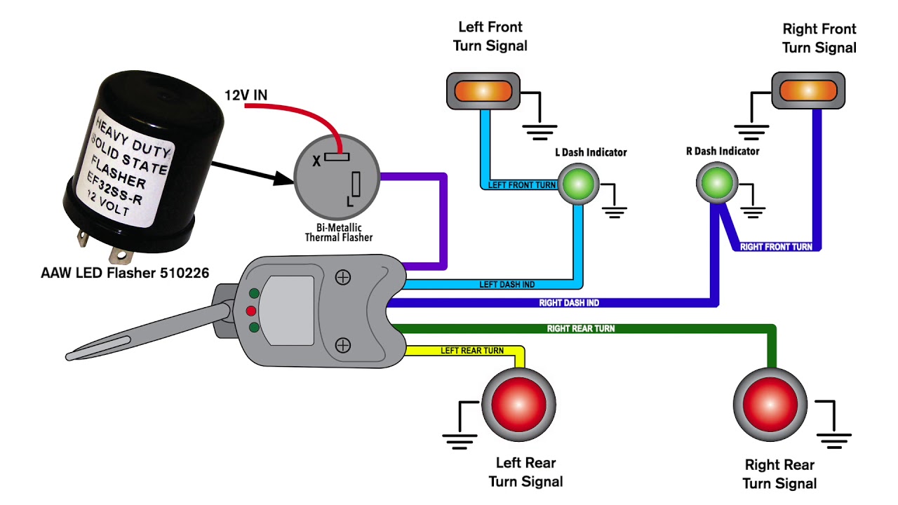
Understanding the turn signal flasher circuit is crucial for anyone who wants to delve deeper into automotive electrical systems. Whether you're tackling a malfunctioning turn signal, customizing your vehicle with aftermarket lighting, or simply seeking a better understanding of how things work, having a clear wiring diagram and knowing how to interpret it is invaluable. This article will provide a detailed breakdown of a typical turn signal flasher wiring diagram, explaining its components, function, and troubleshooting.
Why Bother with a Turn Signal Flasher Wiring Diagram?
Turn signal issues are a common automotive problem. A non-functional turn signal not only leads to failed inspections but, more importantly, poses a serious safety hazard. Having a wiring diagram allows you to trace the circuit, identify faulty components, and perform repairs efficiently. It's also essential for safely adding aftermarket lights (like LED turn signals) or modifying the system for custom builds.
Key Specs and Main Parts of a Turn Signal System
A typical turn signal system consists of the following key components, each playing a vital role:
- Battery: The power source for the entire electrical system, usually a 12V DC system.
- Ignition Switch: Activates the electrical system when the key is turned. Often provides the initial power feed to the flasher unit.
- Flasher Unit (or Relay): This is the heart of the system. It's an electronic or electromechanical device that interrupts the current flow, causing the turn signal lights to blink. Modern vehicles often use solid-state flashers, while older ones use thermal or electromechanical designs.
- Turn Signal Switch (or Multifunction Switch): This switch, usually located on the steering column, allows the driver to select the left or right turn signals. It directs power to the appropriate side of the vehicle.
- Turn Signal Bulbs (or Lamps): These are the lights that illuminate to indicate the intended direction of the turn. They can be incandescent, halogen, or LED.
- Wiring: Connects all the components together, carrying the electrical current. Wire gauge (thickness) is important to handle the current load without overheating.
- Ground Connection (Chassis Ground): Provides a return path for the electrical current, completing the circuit. A good, clean ground connection is essential for proper operation.
- Fuse: A safety device that protects the circuit from overcurrent. If too much current flows, the fuse blows, interrupting the circuit and preventing damage.
Decoding the Wiring Diagram: Symbols, Lines, Colors, and Icons
A wiring diagram is a symbolic representation of the electrical circuit. Understanding the symbols is crucial for accurate interpretation. Here's a breakdown of common elements:
- Lines: Solid lines represent wires. Dashed lines often indicate wires that are shielded or have a special function. The thickness of the line does not represent wire gauge.
- Colors: Each wire in a vehicle typically has a specific color (e.g., red, black, blue, yellow). The diagram will usually have a key indicating the color code. For example:
- Red: Often used for power wires.
- Black: Typically used for ground wires.
- Yellow: Might be used for turn signal wires.
- Symbols:
- Battery: A series of long and short parallel lines.
- Ground: A series of downward-pointing lines, often shaped like a triangle.
- Fuse: A squiggly line inside a rectangle.
- Switch: A break in the line with a movable arm indicating the switch position.
- Bulb: A circle with an "X" inside.
- Flasher Unit: A box with specific input/output terminals (e.g., "X," "L," "P"). The exact symbol can vary.
- Resistor: A zig-zag line.
- Diode: A triangle with a line at its point.
- Connectors: Shown as circles or squares where wires join. Diagrams often indicate the connector number and pin number to help you locate it in the vehicle.
A typical turn signal flasher wiring diagram will show the power source (battery), flowing through a fuse to the ignition switch. From there, it might feed the flasher unit. The flasher unit's output connects to the turn signal switch. When the turn signal switch is activated, it sends power to the appropriate turn signal bulbs on the left or right side of the vehicle. Each bulb then connects to a ground point, completing the circuit.
How the Turn Signal Flasher Works
The flasher unit is the key component that causes the lights to blink. Here's a simplified explanation of how it works:
- Power Input: The flasher unit receives power from the ignition switch (or directly from the battery in some designs).
- Interruption: Inside the flasher unit, a mechanism (either electronic or electromechanical) repeatedly interrupts the current flow. Older thermal flashers used a bimetallic strip that heats up when current flows, bends to break the circuit, cools down, and then reconnects, creating the blinking effect. Solid-state flashers use transistors and timing circuits to achieve the same result.
- Output to Turn Signal Switch: The interrupted current is then sent to the turn signal switch.
- Direction Selection: The turn signal switch directs the blinking current to either the left or right turn signal lights, depending on the driver's selection.
- Ground: The current flows through the bulbs and back to ground, completing the circuit and illuminating the lights.
Real-World Use: Basic Troubleshooting Tips
Using a wiring diagram, you can diagnose common turn signal problems:
- No Turn Signals at All: Check the fuse first. If the fuse is blown, replace it. If it blows again immediately, there's a short circuit somewhere in the system. Use the wiring diagram to trace the circuit and look for damaged wires or components. The flasher unit itself might also be faulty.
- One Side Doesn't Work: Check the bulbs on the non-working side. A burnt-out bulb is a common cause. If the bulbs are good, check the turn signal switch. Use a multimeter to check for voltage at the turn signal switch output when the switch is activated. Also, check the wiring and ground connections on that side.
- Turn Signals Blink Too Fast (Hyperflashing): This usually indicates a burnt-out bulb. When a bulb burns out, the resistance in the circuit changes, causing the flasher unit to blink faster. Replacing the bulb usually solves the problem. However, if you've switched to LED bulbs, you may need to add resistors to the circuit to simulate the load of the original incandescent bulbs.
- Turn Signals Stay On Constantly: This could be a short circuit in the wiring or a faulty turn signal switch. Disconnect the turn signal switch and see if the lights turn off. If they do, the switch is likely the problem.
Safety First: Handling Risky Components
Working with automotive electrical systems can be dangerous if proper precautions are not taken. Here are some safety considerations:
- Disconnect the Battery: Always disconnect the negative terminal of the battery before working on any electrical circuits. This prevents accidental short circuits and shocks.
- Use Proper Tools: Use insulated tools designed for automotive electrical work.
- Inspect Wires Carefully: Look for damaged or frayed wires. Replace any damaged wires.
- Work in a Well-Ventilated Area: Automotive batteries can release hydrogen gas, which is flammable.
- Be Careful with the Flasher Unit: Some older flasher units contain capacitors that can store a charge even after the power is disconnected. Discharge the capacitor before handling the unit.
- Fuses are Important: Never replace a fuse with one of a higher amperage rating. This can overload the circuit and cause a fire.
Understanding your vehicle's turn signal flasher wiring diagram is a valuable skill. By learning to interpret the symbols, understand the circuit's operation, and apply basic troubleshooting techniques, you can diagnose and repair common turn signal problems efficiently and safely.
We have a sample turn signal flasher wiring diagram available for download. It will give you a practical example to further your understanding. Contact us to access the file.