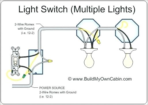
Wiring Diagram For Two Lights On One Switch
Understanding automotive electrical systems is crucial for both basic repairs and advanced modifications. One common task is wiring multiple lights to a single switch. This article provides a detailed wiring diagram explanation, enabling you to confidently tackle such projects. We'll cover everything from the fundamental purpose and key components to troubleshooting tips, all with safety as the top priority. Whether you're adding auxiliary lights, replacing damaged circuits, or just expanding your electrical knowledge, this guide will serve as a valuable resource.
Purpose
The ability to control two or more lights with a single switch is a frequent requirement in automotive applications. This setup is useful for:
- Auxiliary Lighting: Adding driving lights, fog lights, or off-road lights controlled by one switch.
- Replacement: Replacing a failed circuit where the original design used a single switch for multiple lamps.
- Customization: Modifying the lighting system for a specific purpose, such as a custom interior lighting setup.
- Simplification: Reducing the number of switches on a dashboard by consolidating lighting control.
Mastering this configuration is a foundational step towards understanding more complex automotive electrical circuits.
Key Specs and Main Parts
Before diving into the wiring diagram, let's define the key specifications and components involved. The voltage of the system is critical (typically 12V DC in most vehicles). The amperage (current draw) of the lights is also essential for selecting the appropriate wire gauge and fuse rating. Each component must be rated to handle the expected current without overheating or failing.
Main Components:
- Battery: The source of electrical power (12V DC negative ground in most vehicles).
- Fuse: A safety device that protects the circuit from overcurrent. It contains a thin wire that melts and breaks the circuit if the current exceeds a specific value. The fuse rating (in amps) should be slightly higher than the combined current draw of the lights.
- Switch: A device that opens or closes the electrical circuit, allowing or stopping the flow of current. Make sure to use a switch rated for the expected amperage.
- Relay (Optional but Recommended): An electrically operated switch. It uses a small current to control a larger current. A relay is highly recommended when the lights draw a significant amount of current, protecting the switch from overload and providing a cleaner voltage supply to the lights.
- Lights: The lamps being controlled. Specifications include voltage, wattage (power consumption), and type (e.g., incandescent, halogen, LED).
- Wiring: Conductors that carry the electrical current. The wire gauge (thickness) must be sufficient to handle the current without excessive voltage drop. Generally, thicker wires are needed for higher current loads and longer distances.
- Connectors: Devices that join wires together, providing secure and reliable electrical connections.
- Ground Connection: A connection to the vehicle's chassis, providing a path for the current to return to the battery's negative terminal.
Symbols – Wiring Diagram Explained
Understanding the symbols used in a wiring diagram is crucial for accurate interpretation. Here's a breakdown of common symbols:
- Straight Line: Represents a wire or conductor.
- Dotted Line: May represent a wire hidden behind a panel or a wire running along a certain path. Sometimes indicates a connection to ground.
- Circle with a '+' and '-' inside: Represents a battery. The '+' indicates the positive terminal, and the '-' indicates the negative terminal.
- Zigzag Line: Represents a resistor or a load, such as a light bulb.
- Square with a diagonal line inside: Represents a fuse.
- Circle with a line through it: Represents a switch.
- Relay Symbol: Usually a square or rectangle with several terminals labeled with numbers like 30, 85, 86, and 87.
- Ground Symbol: A series of downward-pointing lines connected to a point. Represents a connection to the vehicle's chassis ground.
Color Codes: Wires are often color-coded to aid in identification and troubleshooting. Common colors include:
- Red: Typically used for positive (+) power.
- Black: Typically used for ground (-).
- Yellow: Often used for switched power (power that is only present when a switch is on).
- Blue: Can be used for various purposes, often related to lighting or accessories.
- White: Can be used for various purposes, including ground.
Note: Always consult the specific wiring diagram for your vehicle or application, as color codes can vary.
How It Works
The basic principle behind wiring two lights to one switch is simple: you are essentially creating a parallel circuit. Both lights receive power from the same source and are independently connected to ground. Here's a simplified explanation, assuming use of a relay:
- Power Source: A wire runs from the positive terminal of the battery (often through a fuse) to terminal 30 on the relay.
- Switch Activation: A wire runs from a switched power source (e.g., the ignition switch) to one side of the controlling switch. Another wire runs from the other side of the switch to terminal 85 on the relay. Terminal 86 is connected to ground. When the switch is closed, it completes the circuit, energizing the relay coil.
- Relay Operation: When the relay coil is energized, it closes the internal switch connecting terminal 30 to terminal 87.
- Power Distribution: A wire runs from terminal 87 on the relay and then splits into two separate wires, each running to the positive terminal of one of the lights.
- Ground Connection: Each light has its negative terminal connected to a good ground point on the vehicle's chassis.
When the controlling switch is closed, the relay is energized, which then provides power to both lights simultaneously. This parallel configuration ensures that if one light fails, the other light will continue to operate.
Real-World Use – Basic Troubleshooting Tips
Troubleshooting electrical circuits requires a systematic approach. Here are some common problems and how to address them:
- Lights Don't Work At All:
- Check the fuse: Use a multimeter to verify continuity across the fuse. If blown, replace it with a fuse of the same rating.
- Check the switch: Use a multimeter to verify that the switch is providing continuity when it is in the "on" position.
- Check the relay: Listen for a click when the switch is activated. If no click, the relay may be faulty. You can test the relay by applying 12V to terminals 85 and 86 and checking for continuity between terminals 30 and 87.
- Check the wiring: Look for loose connections, frayed wires, or corrosion. Use a multimeter to verify that power is reaching the lights and that there is a good ground connection.
- One Light Works, the Other Doesn't:
- Check the non-working bulb: Replace the bulb with a known good bulb.
- Check the wiring to the non-working light: Look for loose connections, breaks in the wire, or corrosion. Use a multimeter to check for voltage at the light's positive terminal and continuity to ground at the negative terminal.
- Lights are Dim:
- Check the ground connections: Ensure that the ground connections are clean and secure. Poor ground connections can cause significant voltage drop.
- Check the wire gauge: Ensure that the wire gauge is sufficient for the current draw. Undersized wires can cause voltage drop.
- Check the battery voltage: A weak battery can cause dim lights.
Safety
Working with automotive electrical systems can be dangerous if proper precautions are not taken. Always disconnect the negative terminal of the battery before working on any electrical circuits. High-amp components are particularly risky. Here are some critical safety considerations:
- Battery Disconnection: Always disconnect the negative battery terminal to prevent accidental short circuits.
- Fuse Protection: Always use a fuse in the circuit to protect against overcurrent.
- Proper Wiring Techniques: Use proper crimping and soldering techniques to ensure secure and reliable connections.
- Wire Insulation: Protect wires from abrasion and heat by using proper insulation and routing techniques.
- Avoid Water Exposure: Keep electrical connections away from water and moisture.
- Consult a Professional: If you are not comfortable working on electrical systems, consult a qualified automotive electrician.
Remember to always prioritize safety and double-check your work before reconnecting the battery. Working with electrical systems can be rewarding, but only if done correctly and safely.
We have a detailed wiring diagram for this two lights on one switch configuration available for download. This diagram includes specific wire gauges, fuse ratings, and relay terminal connections. Feel free to download it to assist you with your project.