
Wiring Diagram Fuel Gauge Not Working
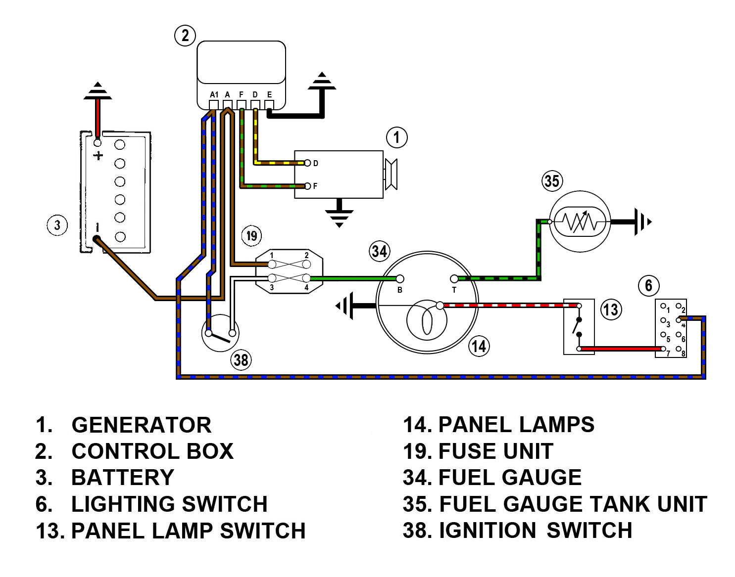
Alright, let's dive into understanding a wiring diagram for a fuel gauge that's decided to take a vacation. Whether you're wrestling with a finicky classic car, tweaking your ride for better performance, or simply want to understand how the fuel gauge system works, this breakdown will equip you with the knowledge to diagnose and potentially fix the issue yourself.
Purpose: Fuel Gauge Wiring Diagram – Your Roadmap to Repair
Why bother with a wiring diagram? Simply put, it's your roadmap to understanding the intricate electrical pathways that make your fuel gauge system tick. It allows you to:
- Diagnose problems: Pinpoint where the electrical signal is being interrupted, leading to an inaccurate or non-functional gauge.
- Repair effectively: Avoid blindly replacing parts and focus on fixing the specific faulty component or wiring section.
- Modify safely: If you're adding an aftermarket fuel gauge or making changes to the system, the diagram ensures you do it without short circuits or damaging components.
- Learn the system: Gain a deeper understanding of automotive electrical systems in general.
Key Specs and Main Parts of a Fuel Gauge System
Before we decipher the diagram, let's identify the key players in a typical fuel gauge system:
- Fuel Tank Sending Unit: This is the variable resistor located inside the fuel tank. A float arm rises and falls with the fuel level, changing the resistance value. This resistance is then sent to the fuel gauge.
- Fuel Gauge: This is the instrument on your dashboard that displays the fuel level. It's essentially a meter that reacts to the varying resistance from the sending unit.
- Wiring: The wires connect the sending unit to the gauge and provide power and ground. These are usually 18-20 gauge wires.
- Power Source: The fuel gauge needs a 12V power source, usually from the ignition switch or a dedicated fuse.
- Ground: A solid ground connection is crucial for both the sending unit and the gauge to function correctly.
Symbols – Decoding the Wiring Diagram
Wiring diagrams use standardized symbols. Here's a breakdown of the most common ones you'll encounter:
- Solid Lines: Represent wires. Thicker lines often indicate main power or ground.
- Dashed Lines: May represent a wire that is part of a harness or shielded.
- Colored Lines: Represent wires, where each color indicates a specific function or circuit. For example:
- Red: Typically 12V power.
- Black: Typically ground.
- Yellow: Can be used for signals or switched power.
- Green: Often used for signals.
- Circles: Represent wire connectors or splices.
- Resistor Symbol (Zigzag Line): Represents the sending unit's variable resistance.
- Ground Symbol (Stacked Triangles): Indicates a connection to the vehicle's chassis, providing a ground path.
- Fuse Symbol (S-shaped line inside a rectangle): represents a fuse.
- Coil Symbol (Spiral): Represents the gauge's internal coil.
- "S" or "Sending Unit": The symbol that represents the fuel sending unit.
The diagram will also use abbreviations to identify wire gauge (e.g., 18GA) and component locations. A key or legend is usually provided with the diagram to explain these abbreviations and symbols.
How It Works: The Flow of Information
Here's a simplified explanation of how the fuel gauge system operates:
- Fuel Level Changes: As the fuel level changes, the float arm in the fuel tank moves up or down.
- Resistance Varies: The movement of the float arm changes the resistance of the sending unit. When the tank is full, the resistance is typically low (e.g., 20 ohms). When the tank is empty, the resistance is high (e.g., 200 ohms).
- Signal Sent: The sending unit sends this varying resistance value to the fuel gauge through a dedicated wire.
- Gauge Reacts: The fuel gauge contains a coil or other mechanism that responds to the changes in current caused by the varying resistance. This causes the gauge needle to move, indicating the fuel level.
- Power and Ground: The entire system needs a stable power supply (typically 12V) and a reliable ground connection to function correctly.
Real-World Use – Basic Troubleshooting Tips Using the Diagram
Let's say your fuel gauge is consistently reading "Empty" even though you know you have fuel. Here's how you might use the wiring diagram for troubleshooting:
- Locate the Diagram: First, obtain the wiring diagram specific to your vehicle's year, make, and model. Generic diagrams are helpful for understanding the principles, but a vehicle-specific diagram is crucial for accurate troubleshooting.
- Check the Fuse: Use the diagram to identify the fuse that protects the fuel gauge circuit. A blown fuse is a common culprit. Replace it and see if the gauge works.
- Inspect the Wiring: Using the diagram as a guide, visually inspect the wiring between the fuel gauge and the sending unit. Look for:
- Damaged wires: Cracked insulation, frayed wires, or corrosion.
- Loose connections: Especially at the fuel gauge, sending unit, and any connectors along the way.
- Poor ground connections: Ensure the ground wires are securely attached to clean metal surfaces.
- Test the Sending Unit: Disconnect the wire leading to the fuel gauge from the sending unit. With a multimeter set to measure resistance (ohms), measure the resistance between the sending unit terminal and ground. Manually move the float arm up and down. The resistance should change smoothly. If the resistance is always zero (short circuit) or infinite (open circuit), the sending unit is likely faulty.
- Check Voltage at the Gauge: Using the diagram, identify the power wire going to the fuel gauge. Turn the ignition on and use a multimeter to measure the voltage between that wire and ground. You should see close to 12V. If not, trace the power wire back to the ignition switch or fuse box, looking for breaks or voltage drops.
- Continuity Test: If the wiring appears to be intact, use a multimeter to perform a continuity test. Disconnect the battery (for safety!). Place one lead of the multimeter on one end of the wire and the other lead on the other end. The multimeter should show close to zero ohms, indicating a good connection. High resistance means a break in the wire.
Important Note: If you suspect a short circuit, always disconnect the battery before probing with a multimeter to avoid further damage.
Safety – Handle with Care!
Working on automotive electrical systems requires caution:
- Disconnect the Battery: Always disconnect the negative battery terminal before working on any electrical components. This prevents accidental short circuits and electrical shocks.
- Fuel Fumes: When working near the fuel tank, be aware of fuel fumes. Work in a well-ventilated area and avoid sparks or open flames.
- Fuel Pump: The fuel pump is usually located inside the fuel tank. Do not energize the fuel pump when the tank is empty, as this can damage the pump.
- Proper Tools: Use insulated tools to prevent short circuits.
The fuel sending unit itself, being inside the fuel tank, is considered a risky component. It’s immersed in gasoline. Never use anything but intrinsically safe tools and lighting when working inside the fuel tank or replacing the fuel sending unit. A single spark can cause an explosion.
Remember that a fuel gauge reading issues might not just be wiring. You should also check the gauge itself by removing it, and connecting it directly to a known-good sending unit.
Diagnosing and repairing a faulty fuel gauge system can seem daunting, but with a clear understanding of the wiring diagram and a systematic approach, you can successfully troubleshoot and fix the problem. Always prioritize safety and consult a professional if you're uncomfortable with any aspect of the repair.
We have the detailed wiring diagram file available for download. It contains specific diagrams that will help in your troubleshooting process. Feel free to download it and use it as a reference while you work on your vehicle.