Wiring Diagram Mass Air Flow Sensor
Alright, let's dive into the world of Mass Air Flow (MAF) sensor wiring diagrams. Understanding these diagrams is crucial for any serious DIY mechanic or car enthusiast looking to diagnose, repair, or even modify their vehicle's air intake system. We're talking about keeping your engine running smoothly and efficiently, and that starts with knowing your MAF sensor inside and out.
Purpose of Understanding MAF Sensor Wiring Diagrams
Why bother learning about MAF sensor wiring diagrams? Simple: it empowers you. Knowing how the MAF sensor is wired allows you to:
- Troubleshoot Issues: Diagnose common problems like lean or rich running conditions, stalling, or poor fuel economy.
- Perform Repairs: Identify and repair broken wires, faulty connectors, or damaged components in the MAF sensor circuit.
- Install Aftermarket Parts: Properly connect performance upgrades, such as cold air intakes or larger MAF housings, without causing electrical problems.
- Gain a Deeper Understanding: Comprehend how your engine management system operates and interacts with the MAF sensor.
Basically, understanding this diagram prevents you from blindly throwing parts at a problem and hoping it goes away. It gives you the power to diagnose accurately and fix efficiently.
Key Specs and Main Parts of a MAF Sensor
Before we jump into the diagram, let's cover the fundamentals. The MAF sensor's job is to measure the mass of air entering the engine. This information is crucial for the Engine Control Unit (ECU) to determine the correct amount of fuel to inject for optimal combustion. Here's a breakdown of the main parts and specs:
- The Sensor Element: This is the heart of the MAF sensor. Common types include hot-wire and hot-film sensors. Hot-wire sensors use a heated wire, while hot-film sensors use a heated film. Both are cooled by the incoming air, and the ECU measures the amount of current needed to maintain a constant temperature, which correlates to the air mass.
- The Housing: This is the physical enclosure that contains the sensor element and directs airflow.
- The Connector: This is the electrical connector that connects the MAF sensor to the vehicle's wiring harness. It typically has 3 to 5 pins.
Key Specs to Consider:
- Voltage Range: MAF sensors typically output a voltage signal that varies between 0 and 5 volts, depending on the airflow.
- Frequency Range: Some MAF sensors output a frequency signal instead of a voltage signal.
- Operating Temperature: MAF sensors are designed to operate within a specific temperature range.
- Calibration: MAF sensors are calibrated to work with specific engines. Using the wrong MAF sensor can cause serious performance problems.
Understanding Wiring Diagram Symbols
Now, let's decode the wiring diagram itself. This is where many people get intimidated, but it's not as scary as it looks. Here's a breakdown of common symbols:
- Lines: Lines represent wires. The thickness of the line doesn't usually indicate anything special; it's mainly for visual clarity.
- Colors: Wire colors are crucial for identification. Common colors include:
- Red: Often indicates a power source (e.g., +12V).
- Black: Usually indicates ground.
- Yellow, Green, Blue: Typically used for signal wires (e.g., MAF signal, Intake Air Temperature (IAT) signal).
- Connectors: Represented by squares or circles, often with numbers indicating pin positions.
- Ground Symbols: Represented by a series of horizontal lines decreasing in size, or a triangle pointing downwards.
- Resistors: Represented by a zig-zag line.
- Sensors: Often represented by a circle with the sensor's abbreviation inside (e.g., MAF).
- ECU: Represented by a rectangle, sometimes labeled "PCM" (Powertrain Control Module).
Important Note: Wiring diagrams vary between vehicle manufacturers and even between different models within the same manufacturer. Always refer to the specific wiring diagram for your vehicle's year, make, and model. Attempting to apply a generic diagram could lead to misdiagnosis and potentially damage your vehicle's electrical system.
How the MAF Sensor Wiring Works
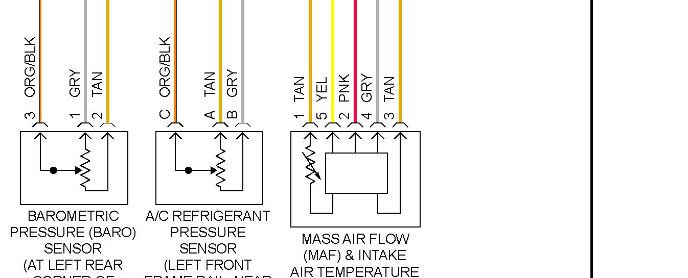
The MAF sensor typically has several wires connected to it, each with a specific function. Let's break down a typical 4-wire MAF sensor setup:
- Power Supply (Usually +12V): Provides the necessary voltage for the sensor to operate. This wire is typically connected to a fused power source.
- Ground: Provides a return path for the electrical current.
- MAF Signal: This wire carries the voltage or frequency signal that represents the measured airflow. This signal is sent to the ECU.
- Intake Air Temperature (IAT) Signal (Sometimes Combined): Many MAF sensors incorporate an IAT sensor. This wire sends the intake air temperature to the ECU, which uses this information to further refine the fuel mixture. Some vehicles have a separate IAT sensor.
The ECU receives the signals from the MAF sensor and the IAT sensor (if applicable). Based on these signals, along with input from other sensors, the ECU calculates the optimal amount of fuel to inject into the engine. A faulty MAF sensor can send incorrect signals to the ECU, leading to a variety of performance problems.
Real-World Use: Basic Troubleshooting Tips
So, how can you use this knowledge in the real world? Here are some basic troubleshooting tips:
- Check for Voltage: Use a multimeter to check for proper voltage at the power supply wire of the MAF sensor connector. If there's no voltage, check the fuse and wiring.
- Check for Ground: Verify that the ground wire has a good connection to the vehicle's chassis.
- Inspect Wiring and Connectors: Look for any signs of damage, corrosion, or loose connections. Pay close attention to the connector pins.
- Test the Signal Wire: With the engine running, use a multimeter or scan tool to monitor the MAF sensor signal. The signal should change as the engine speed increases. A flatlined or erratic signal indicates a problem.
- Use a Scan Tool: A scan tool can read Diagnostic Trouble Codes (DTCs) related to the MAF sensor. These codes can provide valuable clues about the nature of the problem.
Example Scenario: Let's say your engine is running lean and throwing a code related to the MAF sensor. You would start by checking the power and ground to the MAF. If those are good, you'd monitor the MAF signal using a scan tool while revving the engine. If the signal doesn't change or is significantly lower than expected, the MAF sensor itself is likely faulty. If you have a good signal, the issue may be further down the line in the ECU, or there may be a vacuum leak somewhere else.
Safety Considerations
Working with automotive electrical systems can be dangerous. Here are some safety precautions:
- Disconnect the Battery: Always disconnect the negative battery terminal before working on any electrical components. This will prevent accidental short circuits.
- Use Proper Tools: Use insulated tools designed for automotive electrical work.
- Avoid Working in Wet Conditions: Water and electricity don't mix.
- Be Careful Around the Airbag System: Improperly handling the airbag system can cause it to deploy, resulting in serious injury. If you're unsure about working near the airbag system, consult a qualified technician.
The wires around the MAF sensor itself are generally low voltage, the biggest risk is accidentally shorting something to ground while the system is live. However, working on the car involves starting the engine, therefore, the normal precautions such as well-ventilated area need to be taken.
By following these safety guidelines, you can minimize the risk of injury while working on your vehicle's electrical system.
We've covered a lot here, but understanding the MAF sensor wiring diagram is a crucial step in mastering your vehicle's engine management system. This knowledge empowers you to diagnose problems accurately, perform repairs confidently, and even install performance upgrades successfully. Always consult your vehicle's specific wiring diagram before beginning any work. With a little practice and patience, you'll be well on your way to becoming a skilled DIY mechanic.
Remember, we have a comprehensive collection of wiring diagrams available. You can download the MAF sensor wiring diagram specific to your vehicle's year, make, and model for further assistance. Just reach out, and we'll get you set up.