Wiring Diagram Of Alternator And Voltage Regulator
Understanding the wiring diagram of your alternator and voltage regulator is crucial for anyone looking to diagnose charging problems, perform electrical modifications, or simply gain a deeper understanding of their vehicle's electrical system. It's more than just a collection of lines and symbols; it's a roadmap to how your car keeps its battery charged and its electrical components running smoothly. Whether you're tackling a no-start situation, upgrading your electrical system for aftermarket accessories, or just curious about the inner workings of your car, this guide will equip you with the knowledge to decipher these diagrams.
Why This Diagram Matters
Having a solid understanding of the alternator and voltage regulator wiring diagram empowers you in several ways:
- Diagnosis and Repair: Quickly identify faulty wiring, shorts, or open circuits within the charging system. This can save you time and money by avoiding unnecessary parts replacements.
- Electrical Modifications: Safely add aftermarket components like high-powered audio systems, auxiliary lighting, or electric fans by knowing the charging system's capacity and how to properly tap into it.
- System Understanding: Gain a comprehensive grasp of how the alternator, voltage regulator, and battery work together to maintain a stable electrical supply for your vehicle.
- Preventative Maintenance: Identify potential weak points in the wiring that could lead to future failures.
Key Specs and Main Parts
Before diving into the wiring diagram itself, let's define the key components of the charging system and some common specifications to look out for:
Main Parts:
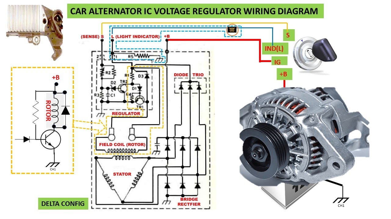
- Alternator: The heart of the charging system, the alternator converts mechanical energy from the engine into electrical energy. It contains a rotor (spinning coil), a stator (stationary coils), diodes (to rectify AC to DC), and often an internal voltage regulator.
- Voltage Regulator: This crucial component maintains a stable voltage output from the alternator, typically around 13.8-14.4 volts in a 12V system. It prevents overcharging the battery and damaging sensitive electrical components. Some are internal to the alternator, while others are external.
- Battery: The energy storage device that provides initial power to start the engine and acts as a buffer for the electrical system.
- Ignition Switch: Often provides the initial signal to the voltage regulator to activate the charging system.
- Wiring Harness: The network of wires that connects all the components of the charging system.
- Fuses and Fusible Links: Protection devices that prevent damage from overcurrent conditions.
Key Specifications:
- Voltage: Typically 12V or 24V in automotive applications.
- Amperage Rating (Alternator): The maximum current the alternator can supply, measured in amps (A). Common ratings range from 60A to 150A or more. Choosing the correct amperage is crucial for meeting the electrical demands of your vehicle.
- Wire Gauge: The thickness of the wires, specified by the American Wire Gauge (AWG) system. Thicker wires can handle more current. Using the wrong gauge can lead to overheating and fire.
- Operating Temperature: The maximum temperature the components and wiring can withstand.
Decoding the Wiring Diagram: Symbols and Conventions
Understanding the symbols and conventions used in the wiring diagram is essential for proper interpretation. Here's a breakdown of common elements:
- Lines: Represent wires. Thicker lines usually indicate wires carrying higher current.
- Colors: Each wire is color-coded for identification. Consult your vehicle's specific wiring diagram for the color codes used. Common colors include red (power), black (ground), blue, green, yellow, and white.
- Symbols:
 Resistor
 Capacitor
 Ground
- Alternator symbol (usually a circle with "ALT" or a stylized representation)
- Voltage regulator symbol (often a rectangle with "VR" or a schematic representation of its internal circuitry)
- Fuse symbol (a zig-zag line enclosed in a rectangle)
- Switch symbol (a line that can be opened or closed)
- Numbers and Letters: Often used to identify specific terminals or connections. Refer to your vehicle's repair manual for their meanings.
Note: Always use the wiring diagram specific to your vehicle's year, make, and model. Generic diagrams can be helpful for understanding the general principles, but they won't accurately reflect the specifics of your car's wiring.
How It Works: A Simplified Explanation
The charging system works in a closed loop to maintain the battery's charge and provide power to the vehicle's electrical components.
- When the engine starts, the alternator's rotor is driven by the engine's belt.
- The spinning rotor generates an alternating current (AC) in the stator windings.
- The diodes within the alternator rectify the AC voltage into direct current (DC).
- The voltage regulator monitors the system voltage and adjusts the alternator's output to maintain a stable voltage (typically 13.8-14.4V).
- If the voltage is too low, the regulator increases the current supplied to the rotor, increasing the alternator's output. If the voltage is too high, the regulator reduces the current to the rotor, decreasing the output.
- The DC voltage from the alternator charges the battery and powers the vehicle's electrical loads.
The wiring diagram shows how these components are interconnected. You'll typically see:
- A heavy-gauge wire connecting the alternator's output terminal to the positive terminal of the battery (often through a fusible link or fuse). This is the main charging wire.
- A ground wire connecting the alternator's case to the vehicle's chassis (providing a good electrical ground).
- A wire from the ignition switch to the voltage regulator (often labeled "IGN" or "S"), which provides the initial signal to activate the charging system.
- A wire from the battery to the voltage regulator (often labeled "BAT" or "A"), which allows the regulator to monitor the battery voltage.
Real-World Use: Basic Troubleshooting Tips
Here are a few common charging system problems and how the wiring diagram can help you diagnose them:
- No Charging: Use a multimeter to check the voltage at the alternator's output terminal with the engine running. If there's no voltage, check the alternator's ground connection, the ignition switch wire, and the main charging wire for continuity and shorts.
- Overcharging: If the battery is constantly boiling or the headlights are unusually bright, the voltage regulator may be faulty. Use the wiring diagram to check the regulator's connections and test its functionality. A faulty ground connection can also cause overcharging.
- Battery Light On: This usually indicates a problem with the charging system. Consult the wiring diagram to trace the circuit connected to the battery light and identify the potential fault.
- Excessive Battery Drain: If the battery drains quickly when the engine is off, there may be a short circuit in the charging system. The wiring diagram can help you isolate the faulty circuit.
Always disconnect the negative battery terminal before working on the electrical system to prevent accidental shorts and damage.
Safety Precautions
Working with automotive electrical systems can be dangerous. Observe the following safety precautions:
- Disconnect the Battery: Always disconnect the negative battery terminal before working on the electrical system.
- Avoid Short Circuits: Be careful not to create short circuits by accidentally touching wires or terminals together.
- Use Proper Tools: Use insulated tools designed for automotive electrical work.
- Be Aware of Capacitors: Some components, such as the alternator and voltage regulator, may contain capacitors that can store a charge even after the battery is disconnected. Discharge them properly before handling the components.
- Work in a Well-Ventilated Area: When working with batteries, work in a well-ventilated area to avoid inhaling potentially harmful fumes.
- Wear Safety Glasses: Protect your eyes from sparks and debris.
The alternator and voltage regulator, while not intrinsically high-voltage, can source substantial current if shorted. This can lead to rapid heating, melting wires, and even fire. Therefore, take extreme care when probing these components. Respect the power you're working with.
We have a detailed wiring diagram available for download. This diagram provides a visual representation of the connections between the alternator, voltage regulator, battery, and other components in a typical automotive charging system. With this diagram, you'll be able to quickly identify the location of specific wires, connectors, and components, making it easier to troubleshoot and repair electrical problems.