Wiring Diagram Turn Signals And Brake Lights
Alright, let's dive into the world of wiring diagrams for turn signals and brake lights. This is a critical system in any vehicle, and understanding its wiring isn't just about fixing a burnt-out bulb. It's about safety, preventing accidents, and potentially saving yourself a hefty mechanic's bill. Whether you're diagnosing a malfunctioning system, adding aftermarket lights, or just expanding your automotive knowledge, this article will guide you through the intricate details.
Purpose of a Wiring Diagram
Why should you care about a wiring diagram? Simple: it's your roadmap to understanding the electrical system. Specifically for turn signals and brake lights, it's invaluable for:
- Troubleshooting Malfunctions: Pinpointing shorts, opens, and incorrect wiring.
- Performing Repairs: Replacing damaged wires, connectors, or components correctly.
- Adding Aftermarket Components: Installing auxiliary lights, trailer wiring, or upgraded control modules.
- Understanding System Operation: Learning how the various components interact to make everything work.
- Modifying or Customizing: Making changes to the system for specific applications, such as converting to LED lighting.
Key Specs and Main Parts
Before we get into the specifics, let's establish some basics. Here's a rundown of the key components you'll encounter in a typical turn signal and brake light circuit:
- Battery: The source of electrical power (typically 12V DC in automotive applications).
- Fuse: A safety device designed to protect the circuit from overcurrent (short circuit). When current exceeds a set limit, the fuse melts, opening the circuit and stopping the flow of electricity. These are rated in Amperes (Amps or A).
- Ignition Switch: Controls power to various circuits when the key is turned. Often provides power to the turn signal circuit.
- Turn Signal Switch (Multi-Function Switch): Located on the steering column, this switch allows the driver to activate the left, right, or hazard (emergency) flashers.
- Brake Light Switch: Typically located near the brake pedal, this switch is activated when the brake pedal is pressed, signaling the brake lights to illuminate.
- Flasher Relay (Turn Signal Flasher): An electromechanical or electronic device that creates the intermittent flashing of the turn signals. Older vehicles use thermal flashers that heat up and cool down repeatedly, causing the flashing action. Newer vehicles use electronic flashers that are more reliable and can handle LED lighting.
- Lights (Bulbs or LEDs): The actual light sources that illuminate to indicate turns or braking.
- Wiring Harness: The collection of wires that connect all the components together. Wires are color-coded to help identify their function.
- Ground (Chassis Ground): The electrical return path for the circuit. The negative terminal of the battery is connected to the vehicle's chassis, providing a common ground point for all electrical components.
- Connectors: Devices that join sections of wiring together. They are used to easily connect and disconnect electrical components for service and replacement.
Understanding Wiring Diagram Symbols
A wiring diagram isn't just a random collection of lines and squiggles. It's a symbolic language that represents the electrical system. Here's a breakdown of common symbols:
- Lines: Represent wires. Thicker lines may indicate larger gauge wires, capable of carrying higher current.
- Color Codes: Wires are almost always color-coded to aid in identification. Common colors include red (power), black (ground), yellow, green, blue, and white. Wiring diagrams will include a legend that explains the color codes used in that specific diagram. For example, "GN" might represent a green wire, and "YE/BK" might represent a yellow wire with a black stripe.
- Circles: Typically represent connections or terminals. Sometimes, a filled circle indicates a ground connection to the chassis.
- Rectangles: Often represent components like switches, relays, or control modules.
- Zigzag Line: Represents a resistor, which limits current flow.
- Coil Symbol: Represents an inductor or solenoid coil, as found in a relay.
- Diode Symbol: A triangle pointing to a vertical line. Diodes allow current to flow in only one direction.
- Fuse Symbol: Looks like a squiggly line enclosed in a rectangle or a line that is broken in the middle.
- Light Bulb Symbol: A circle with an "X" inside.
Always refer to the specific wiring diagram's legend for accurate symbol interpretation. Different manufacturers may use slightly different conventions.
How It Works: A Simplified Explanation
Let's break down the operation of the turn signal and brake light circuits:
Turn Signals
- When the turn signal switch is activated (left or right), it completes a circuit that allows power to flow from the battery, through the fuse, through the flasher relay, and then to the appropriate turn signal lights (front and rear).
- The flasher relay interrupts the current flow, creating the flashing effect. The flasher relay cycles on and off, causing the lights to blink.
- The circuit is completed through the ground, allowing the current to return to the battery.
Brake Lights
- When the brake pedal is pressed, the brake light switch closes, completing a circuit that allows power to flow from the battery, through the fuse, and then to the brake lights.
- The brake lights illuminate as long as the brake pedal is depressed.
- The circuit is completed through the ground, allowing the current to return to the battery.
The hazard lights (emergency flashers) typically have their own circuit that bypasses the turn signal switch and activates all four turn signal lights simultaneously.
Real-World Use: Basic Troubleshooting Tips
Now, let's put this knowledge to practical use. Here are some basic troubleshooting tips using a wiring diagram:
- No Turn Signals or Brake Lights: Check the fuses first! A blown fuse is the most common cause. Use a multimeter to verify continuity.
- One Turn Signal Doesn't Work: Check the bulb. If the bulb is good, use a multimeter to check for voltage at the bulb socket when the turn signal is activated. If there's no voltage, trace the wiring back to the turn signal switch, checking for broken wires or loose connections.
- Both Turn Signals Flash at the Same Time: This could indicate a short circuit or a faulty flasher relay.
- Brake Lights Don't Work: Check the brake light switch. Use a multimeter to verify that the switch is closing when the brake pedal is pressed. Also, check the bulbs and the wiring.
- Turn Signals Flash Too Fast: Often caused by a burnt-out bulb. The reduced resistance in the circuit causes the flasher to operate at a faster rate. It can also be caused by an incompatibility between the flasher relay and the bulbs (e.g., using an incandescent flasher with LED bulbs).
Always use a multimeter to check for voltage and continuity. A multimeter is an essential tool for diagnosing electrical problems.
Pay attention to the ground connections. A poor ground can cause all sorts of strange electrical problems.
Safety Precautions
Working with automotive electrical systems can be dangerous. Here are some important safety precautions:
- Disconnect the Battery: Before working on any electrical system, disconnect the negative terminal of the battery to prevent accidental shorts and electrical shocks.
- Use Proper Tools: Use insulated tools designed for electrical work.
- Work in a Well-Ventilated Area: If you're working with flammable liquids, such as electrical contact cleaner, make sure the area is well-ventilated.
- Be Aware of Airbags: Avoid working near airbag modules unless you are specifically trained to do so. Disconnecting the battery doesn't always disable the airbag system.
- Capacitors: Some electronic components contain capacitors that can store a charge even after the battery has been disconnected. Be careful when handling these components.
The vehicle's battery and charging system can deliver a significant electrical shock! Exercise extreme caution when working near these components.
By understanding the wiring diagram and following proper safety procedures, you can confidently diagnose and repair turn signal and brake light problems on your vehicle.
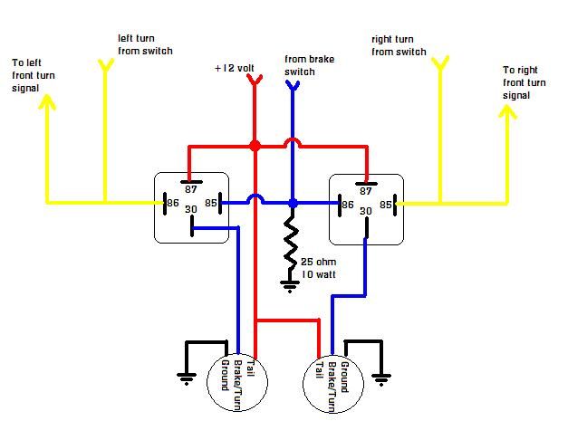
We have a sample wiring diagram available for download. It provides a visual aid to help you understand the concepts discussed in this article.