
Wiring Electric Trailer Brakes Diagram
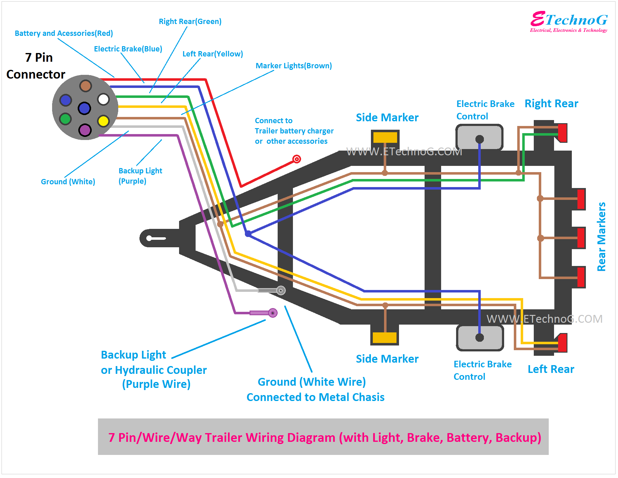
Wiring electric trailer brakes can seem daunting, but with a clear understanding of the system and a reliable wiring diagram, it's a manageable task for the experienced DIYer. Whether you're performing repairs, upgrading your trailer's braking system, or simply seeking to understand how it all works, this guide will provide you with the necessary knowledge and the confidence to tackle this project. We even have a wiring diagram available for download – just ask!
Purpose of Understanding Electric Trailer Brake Wiring
A solid understanding of electric trailer brake wiring is crucial for several reasons:
- Repair and Maintenance: Identifying and resolving wiring issues is essential for maintaining a safe and functional braking system. Faulty wiring can lead to brake failure, posing a significant safety risk.
- Upgrades and Modifications: When upgrading your trailer's braking system, such as adding brakes to an axle or installing a new brake controller, you'll need to be familiar with the wiring to ensure proper integration.
- Troubleshooting: Diagnosing braking problems often involves tracing the electrical circuits and identifying any breaks, shorts, or corrosion. A wiring diagram is invaluable for this process.
- Safety: Above all, understanding how the system works helps ensure that your trailer braking system is safe and reliable, preventing accidents and protecting yourself and others on the road.
- Learning and Knowledge: Even if you don't plan on doing the work yourself, knowing how the system operates can help you better communicate with mechanics and understand their recommendations.
Key Specs and Main Parts of the System
Before diving into the wiring diagram, let's review the key components and specifications of an electric trailer brake system:
Main Components:
- Brake Controller: This unit, typically mounted in the tow vehicle, sends a signal to the trailer brakes based on the tow vehicle's braking activity. It modulates the amount of current sent to the brakes.
- Trailer Connector (Plug): The physical connection point between the tow vehicle and the trailer. Common types are 7-way round pin connectors (most common for trailers with electric brakes), and sometimes 4-way flat connectors (these usually *don't* have electric brake wiring).
- Wiring Harness: The bundle of wires that connects all the components of the brake system, running from the trailer connector to the brakes themselves.
- Electric Brake Assemblies: Located inside each trailer wheel hub, these assemblies convert electrical energy into mechanical braking force. They consist of an electromagnet, brake shoes, and a drum.
- Breakaway Switch: A crucial safety device that activates the trailer brakes if the trailer becomes detached from the tow vehicle. It uses a small battery on the trailer to power the brakes in an emergency.
- Junction Box (Optional): A central point where multiple wires connect, often located on the trailer tongue. Simplifies wiring and troubleshooting.
Key Specifications:
- Voltage: Typically 12V DC (Direct Current).
- Wire Gauge: Refers to the thickness of the wires. Thicker wires (lower gauge numbers) can carry more current. Using the correct gauge is crucial for safety and performance. 12-gauge or 10-gauge wire is common for brake wiring.
- Amperage: The amount of electrical current flowing through the circuit. Each brake assembly draws a certain amount of amperage; the brake controller must be rated to handle the total amperage draw of all the brakes.
Understanding Wiring Diagram Symbols
A wiring diagram is a symbolic representation of the electrical circuit. Understanding these symbols is essential for interpreting the diagram correctly. Here's a breakdown of common symbols:
- Lines: Represent wires. Solid lines typically indicate standard wiring, while dashed lines may represent ground wires or optional connections. The thickness of the line doesn't necessarily represent the wire gauge.
- Circles: Can represent various components, depending on what's inside. They might represent lights, switches, or connectors.
- Rectangles: Commonly represent larger components, such as the brake controller or junction box.
- Ground Symbol: A series of horizontal lines, often resembling a downward-pointing arrow, indicating a connection to ground (the chassis of the trailer, which serves as a return path for the current). Proper grounding is critical for the electric trailer brake system to function correctly.
- Fuse Symbol: A squiggly line enclosed in a rectangle or circle, representing a fuse. Fuses protect the circuit from overcurrent.
- Color Coding: Wire colors are often indicated on the diagram. Standard color coding is as follows:
- Black: Usually 12V+ power.
- White: Ground.
- Blue: Brake signal wire (from brake controller to trailer brakes).
- Brown: Right turn/brake light.
- Green: Left turn/brake light.
- Yellow: Tail/running lights.
- Red: Auxiliary power (e.g., for charging a trailer battery).
The wiring diagram will show how these components are connected, allowing you to trace the flow of electricity and identify potential problems.
How Electric Trailer Brakes Work
Electric trailer brakes operate by converting electrical energy into mechanical braking force. When the brake controller in the tow vehicle senses that the driver is applying the brakes, it sends an electrical signal to the trailer brakes via the blue wire. This signal energizes an electromagnet within each brake assembly. The electromagnet is positioned near a rotating drum or rotor. When energized, the electromagnet is attracted to the rotating surface. This attraction causes the electromagnet to move and engage a lever or cam. The lever or cam then presses the brake shoes against the inside of the drum, creating friction and slowing the trailer wheels. The amount of braking force is proportional to the amount of current sent to the electromagnet by the brake controller, allowing for smooth and controlled braking. The breakaway switch, when activated, directly applies 12V power to the trailer brakes, bypassing the brake controller and providing maximum braking force in an emergency.
Real-World Use: Basic Troubleshooting Tips
Here are some common problems and troubleshooting tips for electric trailer brakes:
- No Brakes:
- Check the trailer connector and tow vehicle connector for corrosion or damaged pins.
- Inspect the brake controller for proper operation and settings.
- Verify that the breakaway switch is not activated.
- Check the wiring harness for breaks, shorts, or loose connections. Use a multimeter to test for continuity.
- Inspect the brake assemblies themselves.
- Weak Brakes:
- Adjust the brake controller settings.
- Check the brake shoes for wear.
- Inspect the magnets for wear or damage.
- Ensure proper grounding of the trailer wiring.
- Brakes Locking Up:
- Check the brake controller settings.
- Inspect the brake assemblies for binding or sticking components.
- Ensure the brake controller is compatible with the trailer brake type.
A multimeter is an indispensable tool for troubleshooting electrical problems. Use it to check for voltage, continuity, and resistance in the various circuits.
Safety Considerations
Working with electrical systems can be dangerous. Here are some safety precautions to keep in mind:
- Disconnect the Power: Always disconnect the trailer from the tow vehicle and disconnect the trailer battery before working on the electrical system.
- Wear Safety Glasses: Protect your eyes from debris and sparks.
- Use Insulated Tools: Use tools with insulated handles to prevent electric shock.
- Work in a Dry Area: Avoid working on electrical systems in wet conditions.
- Fuses: Always use the correct fuse rating for each circuit. Using a fuse with a higher rating can overload the circuit and cause a fire.
- High Voltage Components: While the system operates at 12V, a short circuit can still deliver a dangerous shock.
Important: If you are not comfortable working with electrical systems, consult a qualified mechanic. Improper wiring can lead to brake failure and serious accidents.
With the right knowledge, tools, and a clear wiring diagram, you can successfully maintain and troubleshoot your electric trailer brake system. Remember safety first! And don't forget, we have a detailed wiring diagram available for you to download, making this project even easier!