
Wiring Harness For 4l60e Transmission
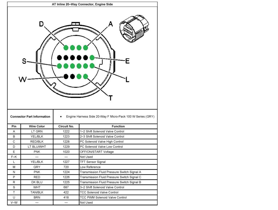
So, you're diving into the world of the 4L60E transmission – a reliable workhorse found in countless GM vehicles. Whether you're wrestling with a no-shift situation, upgrading to a standalone controller, or simply expanding your automotive knowledge, understanding the 4L60E wiring harness is absolutely critical. This article will serve as your guide, breaking down the complexities into manageable chunks and equipping you with the knowledge to diagnose, repair, and even modify this vital component. We have the wiring diagrams and will be providing them to you, so you can follow along and even print for in-shop use.
Purpose: Why Bother Learning This?
Why is understanding the 4L60E wiring harness so important? Here's a few scenarios:
- Troubleshooting Transmission Issues: A faulty wire or connection can mimic a much more serious internal problem. Knowing how to test and trace the wiring can save you time and money.
- Transmission Swaps: If you're swapping a 4L60E into a vehicle that didn't originally have one (like a classic muscle car or off-road project), you'll need to create or adapt the wiring harness.
- Standalone Controller Installation: Using an aftermarket transmission controller gives you greater control over shift points and firmness. This requires understanding and potentially modifying the existing harness.
- General Automotive Education: Expanding your knowledge of automotive electrical systems will make you a more competent and confident DIY mechanic.
Key Specs and Main Parts of the 4L60E Wiring Harness
The 4L60E wiring harness isn't just a random collection of wires; it's a carefully engineered system designed to transmit signals between the transmission and the vehicle's Powertrain Control Module (PCM), or aftermarket controller. Here's a breakdown of the key components and their functions:
- Connector: This is the main interface between the transmission and the vehicle's wiring. It typically contains several pins, each corresponding to a specific sensor or solenoid. The specific pinout (the arrangement of the pins and their assigned functions) is critical to understanding the harness.
- Solenoids: The 4L60E uses several solenoids to control fluid flow and, consequently, gear selection and torque converter lockup. These solenoids are electronically controlled by the PCM/TCM.
- Shift Solenoid A & B: These solenoids, often referred to as SSA and SSB, are responsible for controlling gear selection (1st, 2nd, 3rd, and 4th). By energizing or de-energizing these solenoids in different combinations, the transmission shifts between gears.
- Torque Converter Clutch (TCC) Solenoid: This solenoid controls the engagement of the torque converter clutch. Engaging the TCC locks the engine and transmission together, improving fuel economy at highway speeds.
- Pressure Control Solenoid (PCS): Some later models of the 4L60E (and the 4L65E) use a PCS to electronically control line pressure.
- Sensors: Sensors provide feedback to the PCM/TCM, allowing it to monitor transmission performance.
- Transmission Fluid Temperature (TFT) Sensor: This sensor measures the temperature of the transmission fluid. The PCM uses this information to adjust shift points and torque converter clutch engagement to protect the transmission from overheating.
- Input Speed Sensor (ISS): This sensor measures the speed of the input shaft inside the transmission.
- Output Speed Sensor (OSS): This sensor measures the speed of the output shaft inside the transmission. The PCM/TCM uses the ISS and OSS signals to calculate gear ratio and detect slippage.
- Wiring: The wiring itself is critical. It's essential to use the correct gauge wire for each circuit to ensure proper signal transmission and prevent overheating. Pay attention to the wire color codes, as they're used to identify specific circuits.
- Connectors/Terminals: These are the points where wires connect to the solenoids, sensors, and the main connector. They must be clean, tight, and free of corrosion to ensure a good electrical connection.
Understanding Wiring Diagram Symbols
Wiring diagrams use a standardized set of symbols to represent electrical components and connections. Here are some common symbols you'll encounter in a 4L60E wiring diagram:
- Lines: Lines represent wires. A solid line indicates a direct connection, while a dashed line might indicate a shielded wire or a connection that's part of a larger harness. The thickness of the line generally doesn't indicate wire gauge, but it is useful for tracing the signal.
- Color Codes: Wires are color-coded to help identify them. Common colors include red (power), black (ground), and various other colors for signal wires. The diagram will have a legend explaining the color codes.
- Circles/Dots: A dot where two or more lines intersect indicates a connection. If the lines cross without a dot, it means they are not connected.
- Rectangles: Rectangles often represent components like solenoids, relays, or sensors.
- Ground Symbol: A ground symbol (usually three lines decreasing in length) indicates a connection to the vehicle's chassis ground.
- Connectors: Connectors are often represented by interlocking shapes or a series of squares or circles.
How It Works: Signal Flow and Control
The 4L60E's operation hinges on the PCM (or standalone controller) receiving information from the sensors, processing that data, and then sending signals to the solenoids to control shifting and torque converter lockup.
Here's a simplified overview:
- Sensor Data: The TFT, ISS, and OSS send signals to the PCM, providing information about fluid temperature and transmission speeds.
- PCM Processing: The PCM uses this sensor data, along with information from other sensors like the throttle position sensor (TPS) and vehicle speed sensor (VSS), to determine the optimal shift points.
- Solenoid Activation: Based on the calculated shift points, the PCM energizes or de-energizes the shift solenoids (SSA and SSB) to engage the appropriate gears. The PCM also controls the TCC solenoid to lock the torque converter.
- Feedback Loop: The PCM continuously monitors the sensor data to ensure the transmission is operating correctly and adjusts the solenoid signals as needed.
Real-World Use: Basic Troubleshooting Tips
Okay, let's get practical. Here are a few common troubleshooting scenarios related to the 4L60E wiring harness:
- No Shifting: If the transmission is stuck in one gear, start by checking the shift solenoid wiring. Use a multimeter to verify that the solenoids are receiving power and ground. You can also check the solenoid resistance (should be within a specified range, typically around 20-30 ohms). Also, inspect the wiring harness for damage, corrosion, or loose connections.
- Erratic Shifting: Erratic or harsh shifting can be caused by a faulty TFT sensor, a loose connection in the OSS/ISS circuits, or a problem with the PCS (if equipped). Use a scan tool to read the sensor values and check for any error codes.
- Torque Converter Clutch Issues: If the torque converter isn't locking up properly, check the TCC solenoid wiring and the TCC solenoid itself. A common issue is a broken wire or a faulty solenoid.
- Check Engine Light: If the check engine light is on, scan the PCM for diagnostic trouble codes (DTCs). Many DTCs are directly related to the transmission wiring or sensors.
Using a Multimeter: A multimeter is your best friend when troubleshooting electrical problems. Learn how to use it to check for voltage, continuity, and resistance. Continuity testing is particularly useful for identifying broken wires or loose connections. Resistance testing can help you determine if a solenoid is good or bad.
Safety First: Highlighting Risky Components
Working with automotive electrical systems can be dangerous. Here are some key safety precautions:
- Disconnect the Battery: Always disconnect the negative battery cable before working on any electrical components. This will prevent accidental shorts and potential electric shock.
- Work in a Well-Ventilated Area: Some automotive fluids, such as brake cleaner, can be flammable or toxic.
- Use Proper Tools: Use insulated tools to prevent electrical shock.
- Identify the High-Current Circuits: Be especially careful around the starter motor and alternator wiring, as these circuits carry high current and can cause serious burns.
- Don't Work on a Live Circuit: Unless you absolutely need to, avoid working on circuits while the vehicle is running.
The 4L60E wiring harness, while seemingly complex, is ultimately a system of interconnected wires, sensors, and solenoids. By understanding the purpose of each component, the wiring diagram symbols, and the basic troubleshooting techniques, you'll be well-equipped to tackle a wide range of transmission-related problems. Remember safety is paramount. Always disconnect the battery and use proper tools and techniques when working on electrical systems.
We have the comprehensive 4L60E wiring diagrams ready for you. Contact us for a link to download the file. Good luck with your project!